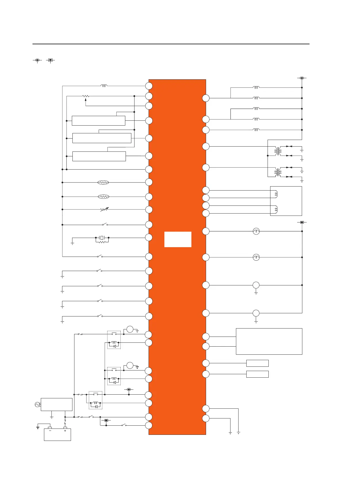
ECM circuit diagram
5-13
ECM circuit diagram
, : Indicate a connection between the symbols.
The circled numbers in the illustration indicate the engine ECM terminal numbers.
T
BZ
P
M
21. Main relay
24. Main switch
22. Rectifier/
regulator
23. Battery
17. Starter
relay
18. Starter motor
20 A
30 A
20 A
50 A
25. Engine start
switch
20. High-pressure
fuel pump
19.
High-
pressure
fuel pump
relay
41. Reprogramming connector
40. YDIS
34. ISC
valve
2. TPS
3. Air pressure sensor
27. Fuel injector #1
28. Fuel injector #4
29. Fuel injector #2
30. Fuel injector #3
31. Vapor shut-off valve
32. Ignition coil #1, #4
33. Ignition coil #2, #3
35. Oil pressure alert indicator
26. Engine
ECM
36. Overheat alert indicator
37. Alert buzzer
38. Tachometer (6Y5/6Y7)
39. 6Y8 network
4. Water pressure sensor
5. Speed sensor
6. Ground
7. Air temperature sensor
8. Thermo sensor
9. Trim sensor
10. Water detection switch
11. Knock sensor
12. Shift position switch
13. Engine shut-off switch
14. Oil pressure switch
15. Trolling switch (UP)
16. Trolling switch (DN)
1. Pulser coil
42
43
39
48
49
38
14
40
41
4
19
25
21
26
24
44
35
15
34
5
27
9
8
7
18
1
47
45
46
37
36
50
33
32
23
17
12
13
30
11
20
28
29
16