2 Installation and Commissioning, IRC5
2.9.5. Installation of PMC-card for Force Control Function
1173HAC021313-001 Revision: K
© Copyright 2004-2008 ABB. All rights reserved.
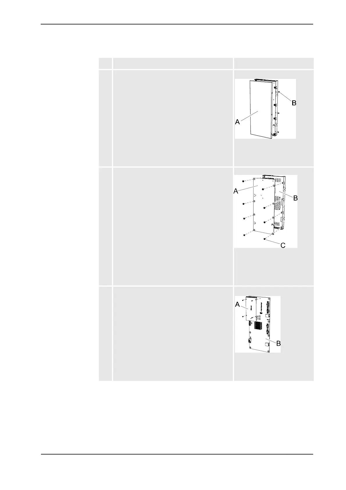
4. Remove the six attachments screws on the sides of
the axis computer, and remove the back cover.
xx0500002134
• A: back cover
• B: attachment screw
(6pcs)
5. Remove the eight attachment screws holding the
board to the front cover, and lift out the board.
xx0500002137
• A: axis computer board
• B: front cover
• C: attachment screw
(8pcs)
6. Mount the PMC-card according to the picture, and
secure it with the four attachment screws.
xx0500002138
• A: PMC-card with
attachment screws
• B: axis computer board
Action Note/illustration
Continued
Continues on next page