Agilent 5DX Service Guide 6-19
5DX Series 3 Pneumatic Subsystem Components
6. Using a 7/16-inch hex wrench, remove the shaft nut holding the Encoder. Refer
to Figure 6-13. Retain the shaft nut for later use.
7. Remove the Encoder.
8. Place the shaft of the new Encoder through the hole in the Encoder Bracket.
9. Using a 7/16-inch hex wrench, reinstall the nut removed in 6
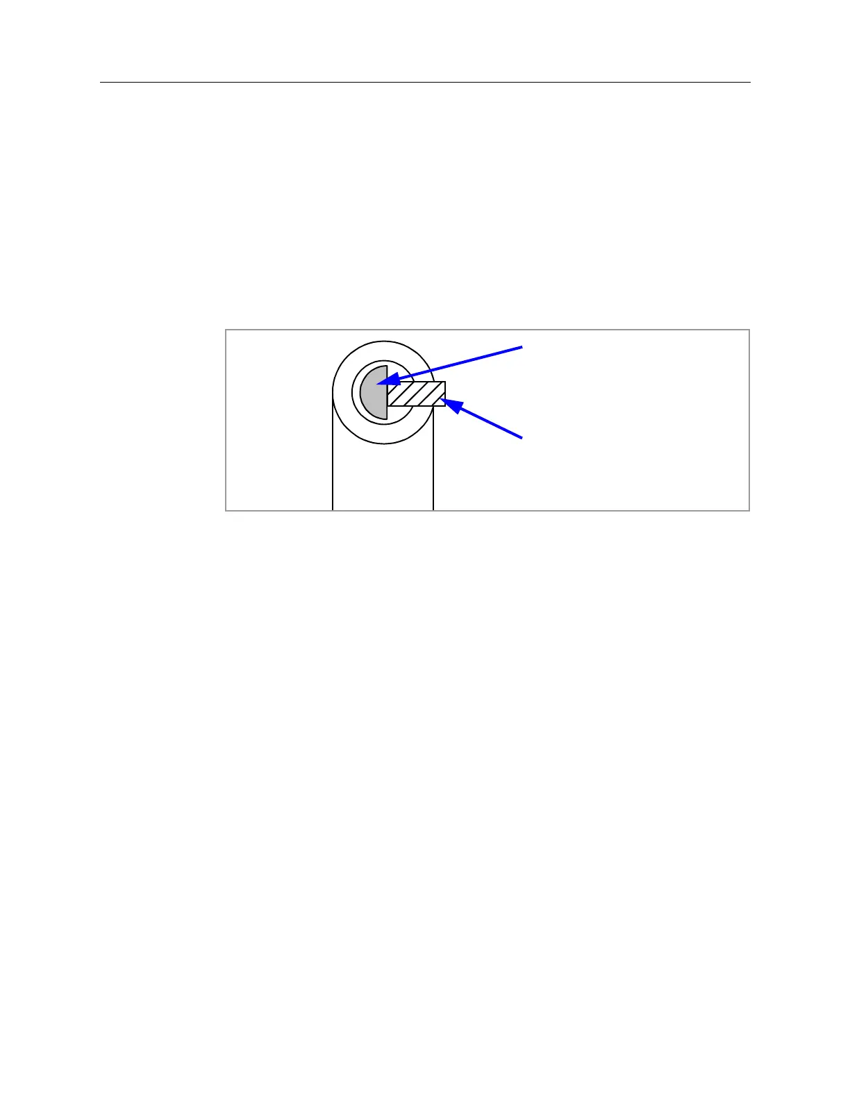
10. Place the shaft of the new Encoder through the hole in the Encoder Arm
Bracket aligning the flat side of the shaft with the Encoder Set Screw, as shown
in Figure 6-14.
Figure 6-14: Positioning the Encoder Set Screw
11. Leave a 0.050-inch gap between the shaft nut and the Encoder Arm Bracket.
12. Using a 5/64-inch hex wrench, tighten the Encoder Set Screw.
13. Replace the Encoder Cover using a 1/6-inch hex wrench and the two screws
removed in 3 on page 6-18.
14. Using a 5/32-inch hex wrench, reinstall the two screws removed in 2 on page
6-17.
15. The Encoder position needs to be set. Refer to the Setting the Positions for
the Encoder procedure on page 6-20.
Set Screw
Encoder Shaft
 Loading...

