8-14 Imaging Subsystem
Imaging Subsystem Components 5DX Series 3
Fields of View (Banks 1-3)
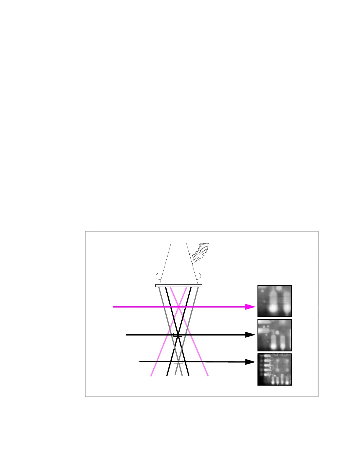
The Slice image is only a small portion of the panel under test. The Field of View
(FOV) represents the area size in mils of the slice image. Figure 8-8 shows how
the size of the image changes with respect to the FOV. In the 200 FOV the image is
a 0.200-inch by 0.200-inch portion of the panel, while in the 650 FOV the image is
a 0.650-inch by 0.650-inch portion of the panel. The smaller the FOV, the greater
the magnification.
When the FOV changes a couple of things happen:
• a different Bank of the X-ray Scan Controller is selected,
• the height of the panel in the Z-Axis changes, and
• the deflection of the Electron Beam changes.
As required, Banks 1 through 3 are loaded with information about three FOVs.
The System Controller issues commands to the Interface Card which in turn sets
the appropriate Bank select inputs to the X-ray Scan Controller. The magnitude of
the deflection is defined by the values of the FOV’s look-up table loaded into the
X-ray Scan Controller’s memory. Referring to Figure 8-8, the different FOVs have
different circle diameters.
Figure 8-8: Images from Various Fields-of View (FOV)
200
400
650
Field of View (FOV)
X-ray Image
 Loading...

