Drop and insertDrop and insert
Timing SourceTiming Source
FollowsFollows
Select the source for the transmitter.
OnOn: transmits the received data which the data generated in the Network Master
has added.
OffOff: transmits the data generated in the Network Master.
Select the clock source.
InternalInternal: Internal clock of the module
ExternalExternal: The clock provided from the Ext Clock connector
ReceivedReceived: The clock generated from the received signal
When ExternalExternal or ReceivedReceived is set, the right hand lamp indicates whether clock
is detected or not.
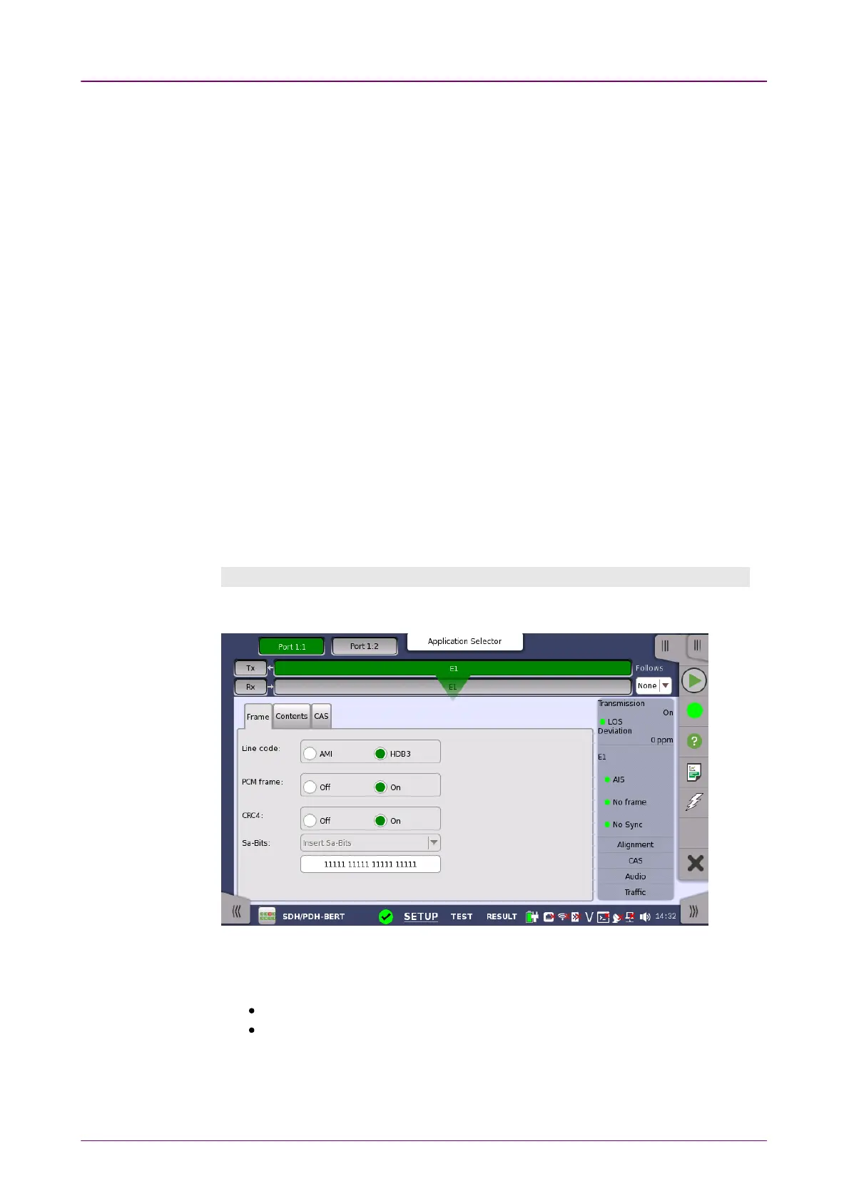
55..33..11..22 E1 Signal SetupE1 Signal Setup
Touching the navigation area button which represents the transmitter's E1 layer
will display the screen.
To make the Port 2 transmitter follow the Port 1 transmitter (i.e. copy its
settings) when using Port 1 and Port 2, touch the drop-down menu in the
navigation area and select the Tx1Tx1. The Port 2 settings continue to follow the
Port 1 transmitter change. The default setting is NoneNone. Note that the Port 1
transmitter cannot follow the Port 2 transmitter.
Frame tab pageFrame tab page
The FrameFrame tab page contains the following parameters:
Line codeLine code
Use the Line codeLine code radio buttons to select transmission line code.
HDB3HDB3: High-Density Bipolar Order 3
AMIAMI: Alternate Mark Inversion
PCM framePCM frame
Use the PCM framePCM frame radio buttons to enable (OnOn) or disable (OffOff) insertion of
PCM frame in the transmitted signal.