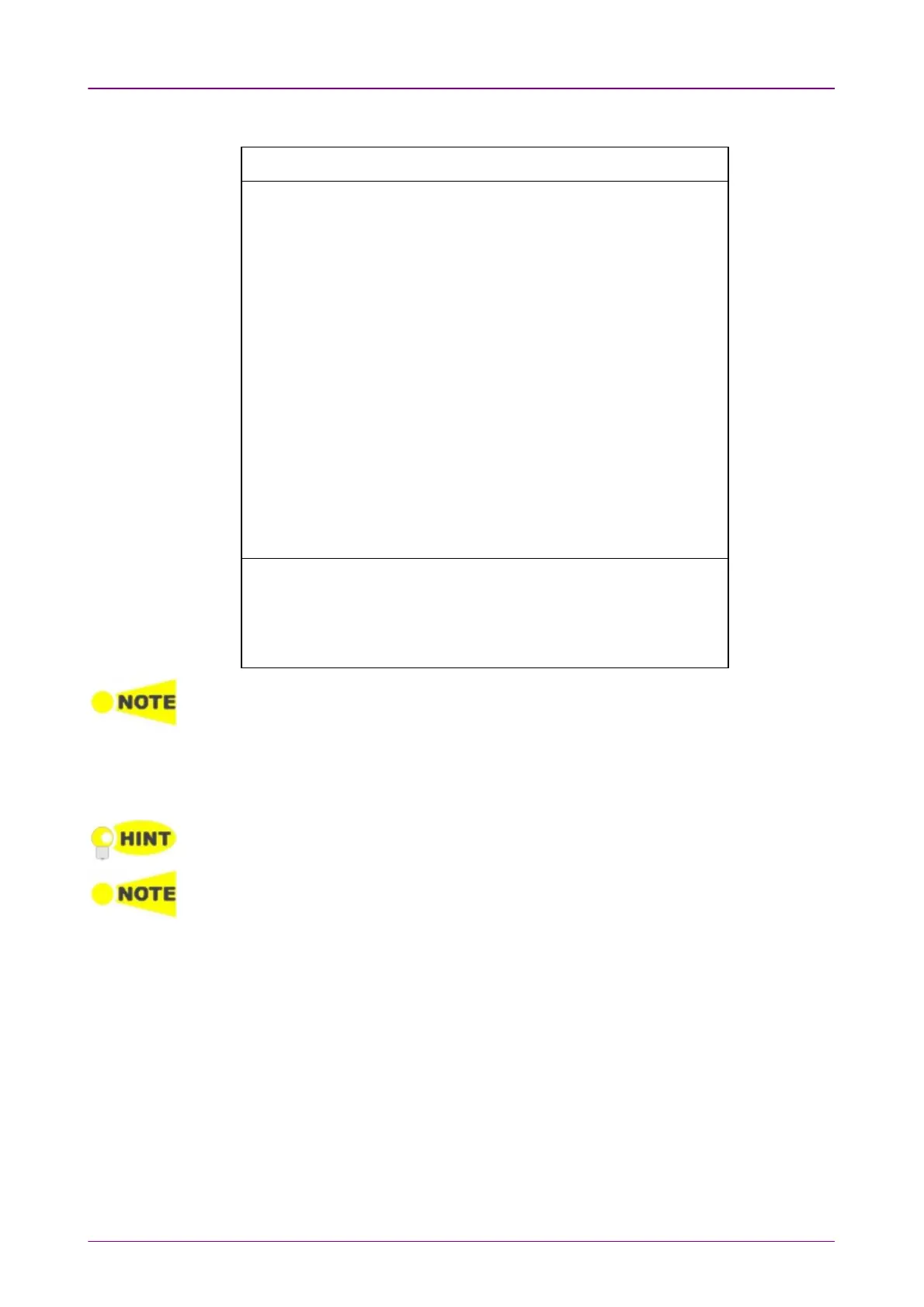
PCM frame is formed by 16 E1 frames. Frame structure is shown below.
Frame Frame
numbernumber
Bits 1 to 8 of the frame (Timeslot 0)Bits 1 to 8 of the frame (Timeslot 0)
11 22 33 44 55 66 77 88
00 C1 0 0 1 1 0 1 1
11 0 1 A Sa Sa Sa Sa Sa
22 C2 0 0 1 1 0 1 1
33 0 1 A Sa Sa Sa Sa Sa
44 C3 0 0 1 1 0 1 1
55 1 1 A Sa Sa Sa Sa Sa
66 C4 0 0 1 1 0 1 1
77 0 1 A Sa Sa Sa Sa Sa
88 C1 0 0 1 1 0 1 1
99 1 1 A Sa Sa Sa Sa Sa
1010 C2 0 0 1 1 0 1 1
1111 1 1 A Sa Sa Sa Sa Sa
1212 C3 0 0 1 1 0 1 1
1313 E 1 A Sa Sa Sa Sa Sa
1414 C4 0 0 1 1 0 1 1
1515 E 1 A Sa Sa Sa Sa Sa
Sub multiframe (SMF) I: Frame number 0 to 7, II: Frame number 8 to 15
E: CRC4 error indication bits (FEBE)
Sa: Spare bits
C1 to C4: Cyclic Redundancy Check-4 (CRC4) bits
A: Remote Alarm Indication (RAI)
When PCM frame is set to Off, many of the following transmitter parameters are
insignificant.
CRC4CRC4
Use the CRC4CRC4 radio buttons to enable (OnOn) or disable (OffOff) CRC4 in the
transmitted signal contained in the PCM Frame.
If you are uncertain whether the CRC4 should be selected or not, it is recommended to
enable the CRC4.
If Drop and InsertDrop and Insert of the total contents of a receiver is selected and the signal contains
CRC4, it is possible to either Bypass or Insert Sa-Bits.
Sa-BitsSa-Bits
Use the drop-down menu above the setup field to select whether or not to
Insert Sa-BitsInsert Sa-Bits or Bypass Sa-BitsBypass Sa-Bits (this is only relevant when Drop and insertDrop and insert is
set to OnOn).
You can set the Sa-Bits value of the non-FAS words in the transmitted signal
when containing PCM Frame/CRC4. Touch the Sa-BitsSa-Bits setup field to open the
setup dialog box.