FollowsFollows
TerminateTerminate
Used when the instrument is used as a tester and the receiver is the only
device connected to the line. The input impedance is nominal.
MonitorMonitor
Used when connecting to protected monitoring points. The input impedance
is nominal.
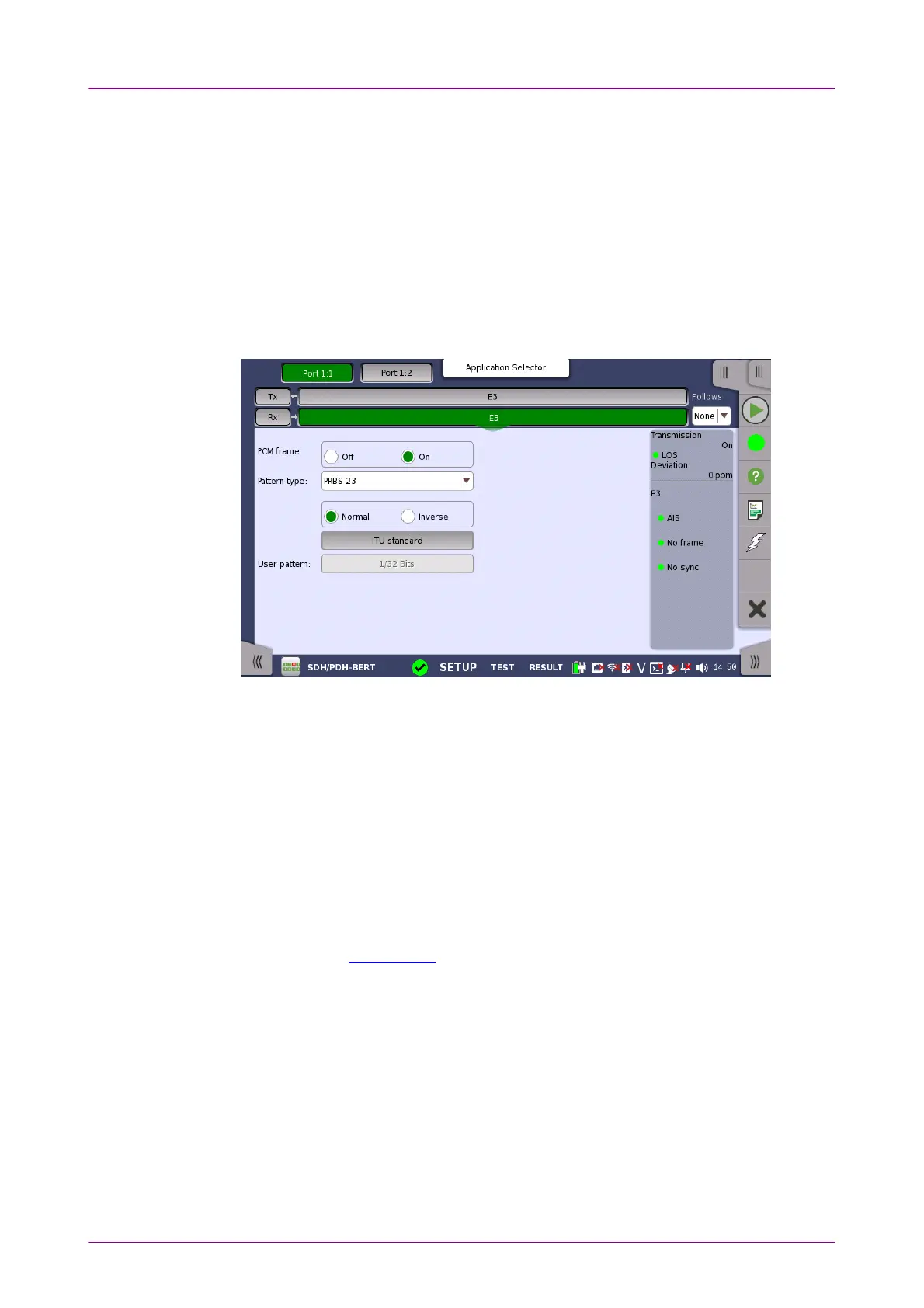
55..55..22..22 E3 Signal SetupE3 Signal Setup
Touching the navigation area button which represents the receiver's E3 layer
will display the screen shown below.
To make the currently selected receiver follow either the transmitter or Port 1
receiver (i.e. copy its settings), touch the drop-down menu in the navigation
area and select the relevant value. The receiver settings continue to follow the
change of either the transmitter or Port 1 receiver. The default setting is NoneNone.
Note that the Port 1 receiver cannot follow the Port 2 receiver.
PCM framePCM frame
Use the PCM framePCM frame radio buttons to enable (OnOn) or disable (OffOff) the status of
the PCM frame.
Pattern typePattern type
Select the requested pattern. Available patterns are the same as the transmitter
setup. Refer to Pattern type in "E1 Setup and Status".
Touch 'Normal' or 'Inverse' pattern type.
Touching the 'ITU standard' button will apply ITU-T O.150 recommended
Pattern typePattern type for 34 Mbit data rates (PRBS 23 Inverse).
User patternUser pattern
User pattern field is enabled if Pattern type is set to User [32] bitUser [32] bit or User [2084]User [2084]
bitbit. Touch the User patternUser pattern field and use the launched Pattern EditorPattern Editor dialog box
to define the user pattern. Depending on the selected pattern type, different
user pattern setup options will be available.
The length can be any length from 1 bit to 32 bits or from 1 bit to 2048 bits.