FECFEC
TransceiverTransceiver
Multi lane mappingMulti lane mapping
InternalInternal
ExternalExternal
GPSGPS
ReceivedReceived
IEEE 1588v2IEEE 1588v2
ReceivedReceived appears when the interface type is set to SFPSFP, SFP+SFP+, SFP28SFP28, QSFP+QSFP+,
QSFP28QSFP28 or CFP4CFP4
IEEE 1588v2IEEE 1588v2 appears when the interface type is set to ElectricalElectrical SFPSFP, or SFP+SFP+.
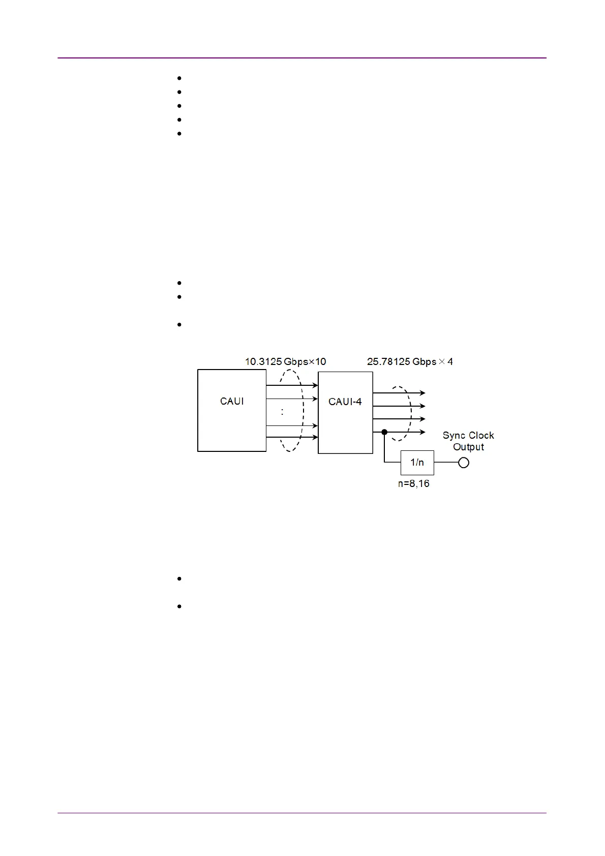
Sync PortSync Port
This item appears when using MU100011A and Interface Type is set to SFP28SFP28,
QSFP28QSFP28 or CFP4CFP4. Selects the output of Sync Clock Output connector on
MU100011A panel.
OffOff: does not output the clock.
1/81/8: outputs 1/8 divided clock of the data synchronized clock (approximately
3.222 GHz).
1/161/16: outputs 1/16 divided clock of the data synchronized clock (approximately
1.611 GHz).
Block Diagram of MU100011A Tx Part (QSFP28, CFP4)
FEC enableFEC enable
This setting appears when using MU100011A and Interface Type is set to
SFP28SFP28, QSFP28QSFP28 or CFP4CFP4.
OnOn: The calculated forward error correction data will be added to the 25G
Ethernet frame and the 100G Ethernet frame.
OffOff: FEC is not added to the 25G Ethernet frame and the 100G Ethernet frame.
Displays the Transceiver information.
In case of 40G or 100G interface, touching the Lane MappingLane Mapping button launches
the following dialog box.