Columns areColumns are
"AND'ed", rows are"AND'ed", rows are
"OR'ed"."OR'ed".
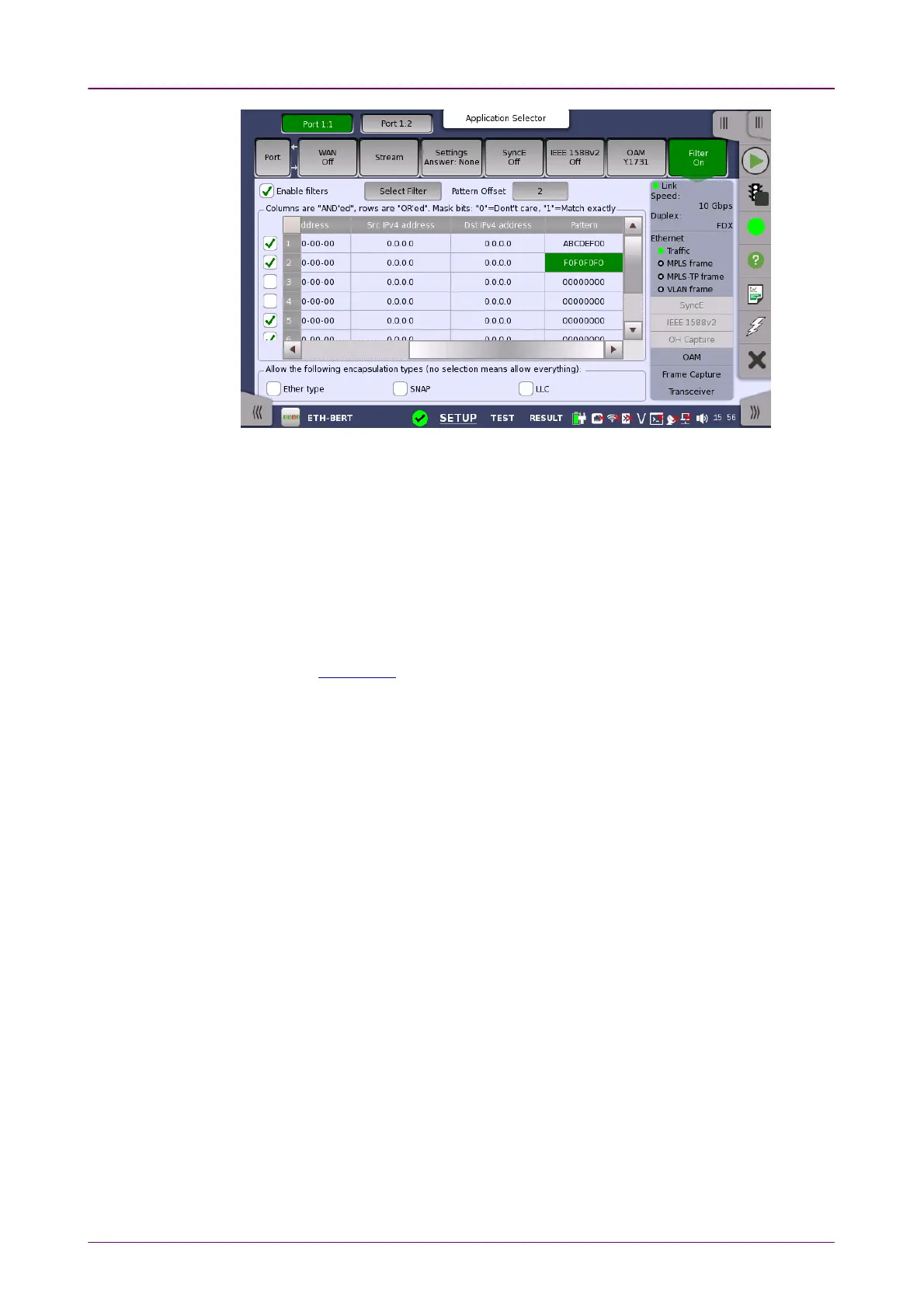
This screen allows you to set up filters and masks for the reception of Ethernet
frames. It can also be used to inspect the current status of the selected port.
The configuration options available in the setup area of the screen are
described below. The status information is described in a separate section.
Enable filtersEnable filters
Select this check box to be able to set up new filters or make changes to the
existing ones.
Select FilterSelect Filter
Opens the dialog box to set target fields to be filtered.
Pattern OffsetPattern Offset
The button will be enabled if PatternPattern is selected in Select Filter dialog box. Set
the number of bytes counted from top of destination MAC address byte.
FollowsFollows
It is possible to let the Port 2 copy the setup from Port 1 by touching the
FollowFollow button. When this button is displayed in green, Port 2 continues to
follow Port 1 change. This button appears when the Port 1 settings can be copy
to Port 2.
The filter and mask table shows the currently existing filters. There are 8 rows,
each representing a filter which (when enabled) is applied to each received
frame. Each filter is composed as a set of values and/or masks (e.g. MAC
destination address, IP addresses etc.). If all values in at least one enabled
row/filter matches, the frame will pass.
If the mask for a specific value is enabled, only bits that are "1"/on are
compared to the frame. For instance, if MAC Destination value is '00-12-34-56-
78-9A' and the mask is set to '00-FF-00-FF-FF-FF', only frames with MAC
addresses 'XX-12-XX-56-78-9A' will pass.
To specify the set of values and/or masks available for each filter (i.e. the
columns of the table), touch the Select FilterSelect Filter button. This will launch the filter
editor dialog box, which contains a number of check boxes for enabling filters
and masks on different addresses.