Module PresentModule Present
TransceiverTransceiver
InformationInformation
When the capture is complete, you can save the captured data as a PCAP file,
which can be used by a variety of open-source decoding tools. You can also
save the data and then view them on the Network Master.
Touching the SaveSave button allows you to create a PCAP file and view the data on
the Network Master. Touching the ViewView button allows you to view the data on
the Network master.
When saving capture files using the MX100001A Remote Control Software, the
destination folder is automatically set to the "Internal" folder of the Network Master.
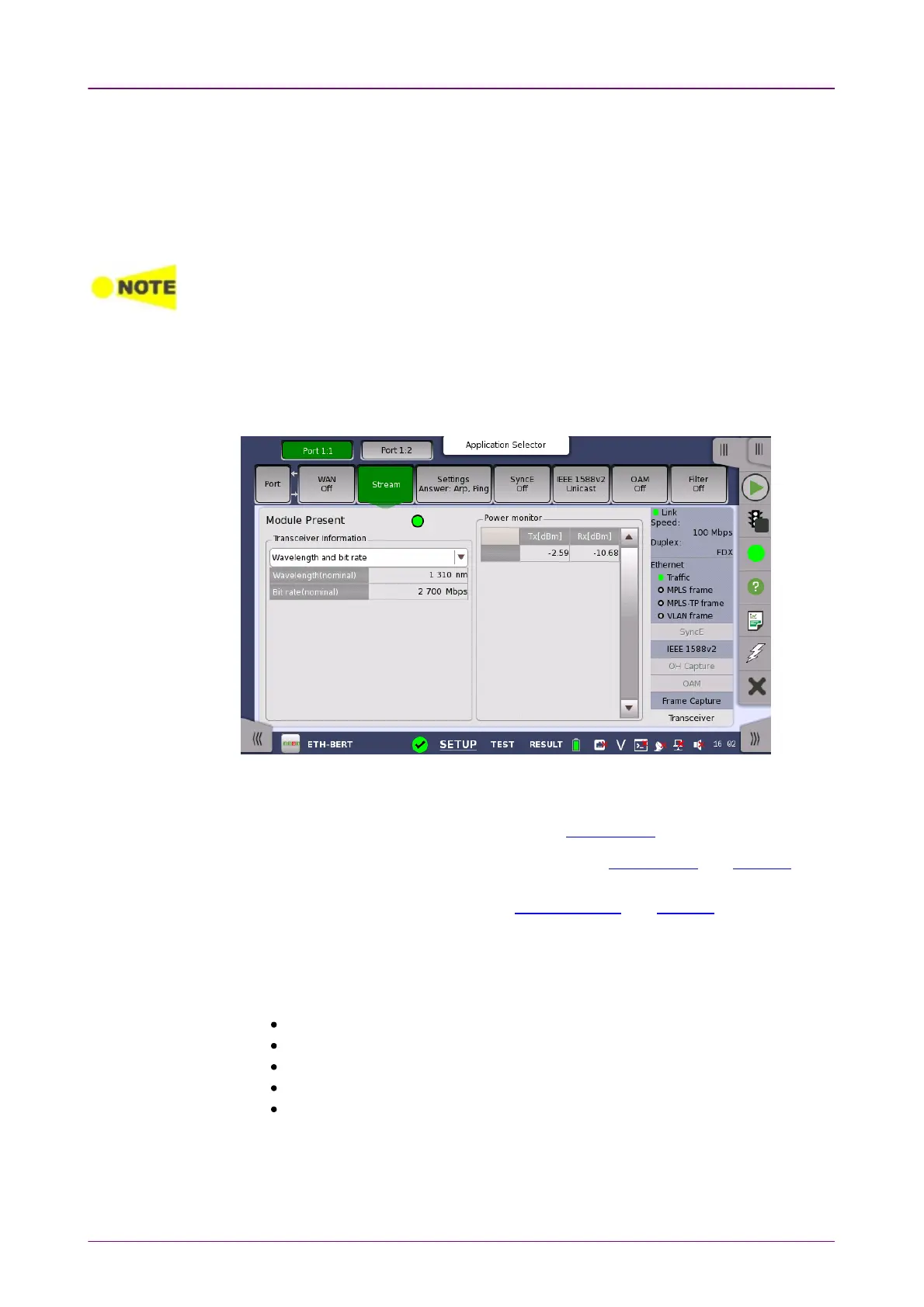
66..11..33..99 TransceiverTransceiver
Touching the TransceiverTransceiver button in the status area of the Ports SetupPorts Setup screen
displays the status shown below.
This screen presents status information about the optical transceiver (Pluggable
module installed on the connector panel).
When the optical transceiver is SFP or SFP+, I2C analysisI2C analysis appears.
When the optical transceiver is QSFP+ or QSFP28, I2C analysisI2C analysis and SettingsSettings
appear.
When the optical transceiver is CFP4, MDIO analysisMDIO analysis and SettingsSettings appear.
GreenGreen indicates that an optical transceiver is currently mounted.
Select the information from pull down menu. AlarmAlarm and Output controlOutput control appear
in case of 40GbE or 100GbE.
AlarmAlarm shows the alarm status.
Wavelength and bit rateWavelength and bit rate shows the nominal wavelength and bit rate.
ComplianceCompliance shows the available standards.
Vendor informationVendor information shows the data stored in the optical transceiver.
Output controlOutput control allows to select lanes to insert alarm/errors.
Tune wavelengthTune wavelength
When the optical transceiver is a tunable SFP, the following items are displayed
for Wavelength and bit rateWavelength and bit rate.