Measurement Result ExampleMeasurement Result Example
nn 1 2 3 4 5 6
δδ
nn
0.1 0 0.05 0 0.2 0
DeviationDeviation 0.1 0 0.05 0 0.2 0
Phase errorPhase error 0.1 0.1 0.15 0.15 0.35 0.35
The difference between two BNC cable lengths makes time difference of 1PPS
signals. Therefore it affects the phase error measurement result. You can set the
correction of the time difference caused from the cable length difference at
1PPS cable correction1PPS cable correction in the Control screen.
Filtered TE displays the phase error passed through the 0.1 Hz bandwidth low
pass filter. The phase error is displayed with suppressed noise.
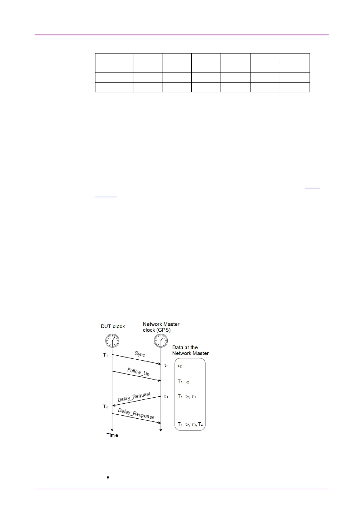
OWD MeasurementOWD Measurement
This part explains how to measure the OWD. To perform the OWD
Measurement, select both of Enable IEEE1588v2Enable IEEE1588v2 and Slave modeSlave mode on the IEEE
1588v2 screen.
1. DUT (Device Under Test) sends
Sync
message to Network Master. T
1
is the
timestamp of DUT at the time
Sync
message has been sent. When not using
Follow_Up
message, T
1
is notified to Network Master by
Sync
message.
2. τ
2
is the timestampe of Network Master at the time
Sync
message has
arrived.
3. If using
Follow_Up
message, T
1
is notified to Network Master by
Follow_Up
message.
4. Network Master sends
Delay_Request
message to DUT. τ
3
is the timestamp
of Network Master at the time
Delay_Request
message has been sent.
5. T
4
is the timestampe of DUT at the time
Delay_Request
message has arrived.
6. Master clock sends
Delay_Response
message and notifies T
4
to Network
Master.
The OWD calculation formula are
below.
Sync OWD = τ
2
- T
1
Delay_Request OWD
= T
4
- τ
3
OWD contains the delay of the optical fiber cable between DUT and Network
Master. TEs (Time error) that the cable delay is subtracted from OWD are
defined as:
TE1= −1 × (Sync OWD) + Δms