6-28 BE1-951 Reporting and Alarm Functions 9328900990 Rev L
A logic input can be used to reset the target. Using BESTCOMS, select Reporting and Alarms from the
S
creens pull-down menu. Then select the Fault Recording tab. The logic input can be connected by
selecting the Logic button in the Target Reset pane. When the logic input becomes TRUE, the target is
reset.
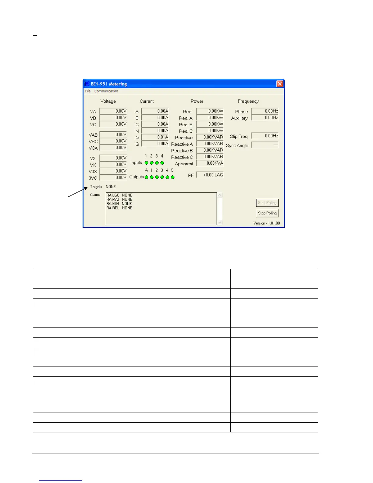
BESTCOMS can also be used to review targets after an operation by selecting Metering from the R
eports
pull-down menu. Targets are shown on the Metering screen. Refer to
Figure 6-15.
P0032-19
07-25-05
Figure 6-15. Metering Screen
Table 6-15 provides the possible targets, which may be displayed in the Metering screen.
Table 6-15. Targets as Displayed
IEEE Device Number Definition
24 Overexcitation
27 ABC Phase Undervoltage
27BUS, 27N, 27-3BUS (27X fundamental, 3V0, 3
rd
harmonic) Auxiliary Undervoltage
32 Directional Power
47 Negative-Sequence Voltage
50/150 ABC, Q or 1, N or G Instantaneous Overcurrents
51 ABC, Q, N or G; 151 ABC, N or G Time Overcurrents
59 ABC Phase Overvoltage
59/159BUS, 59N, 59-3BUS (59/159X fundamental, 3V0, 3
rd
harmonic) Auxiliary Overvoltage
60FL Fuse Loss
62/162 Logic Timers
67T ABC Q, N or G; 167T ABC, N or G Directional Time Overcurrents
67/167 ABC, Q or 1, N or G
Directional Instantaneous
Overcurrents
81/181/281/381/481/581 Frequency
BF Breaker Failure