13-30 BE1-951 Testing and Maintenance 9328900990 Rev L
Step 5: With three-phase voltage still applied, increase the A-phase current until OUT1 closes. Swing
the angle of the applied current +90 degrees and -90 degrees away from the 80-degree
positive- sequence line angle. Verify that OUT1 opens at approximately 170 degrees I lag E and
350 degrees I lag E. Out1 should remain closed from 170 through 80 to 350 degrees I lag E
(defined as forward trip direction)
Negative-Sequence Voltage Polarizing, Phase Overcurrent Elements
Step 6: Apply a 120 Vac, three-phase voltage source at nominal frequency to Terminals C13 (A-phase),
C14 (B-phase), C15 (C-phase), and C16 (Neutral). Reduce the A-phase voltage by 1/3.
Transmit M-V command or view HMI Screen 3.4 to verify that negative-sequence voltage is
greater than 1 volt.
Step 7: Apply 0 amp A-phase current at an angle of 80 degrees I lag E (same as positive-sequence line
angle) and slowly increase the current until OUT1 closes. Decrease A-phase current until OUT1
just drops out. Pickup will occur within ±2 percent of the 50TP pickup setting. Dropout will occur
at 93 to 97% of actual pickup. Verify 67A target on the HMI.
Step 8: With the same voltage still applied, increase the A-phase current until OUT1 closes. Swing the
angle of the applied current +90 degrees and -90 degrees away from the 80-degree positive-
sequence line angle. Verify that OUT1 opens at approximately 170 degrees I lag E and 350
degrees I lag E. Out1 should remain closed from 170 through 80 to 350 degrees I lag E (defined
as forward trip direction)
Negative-Sequence Voltage Polarizing, Negative-Sequence Overcurrent Elements
Step 9: Using
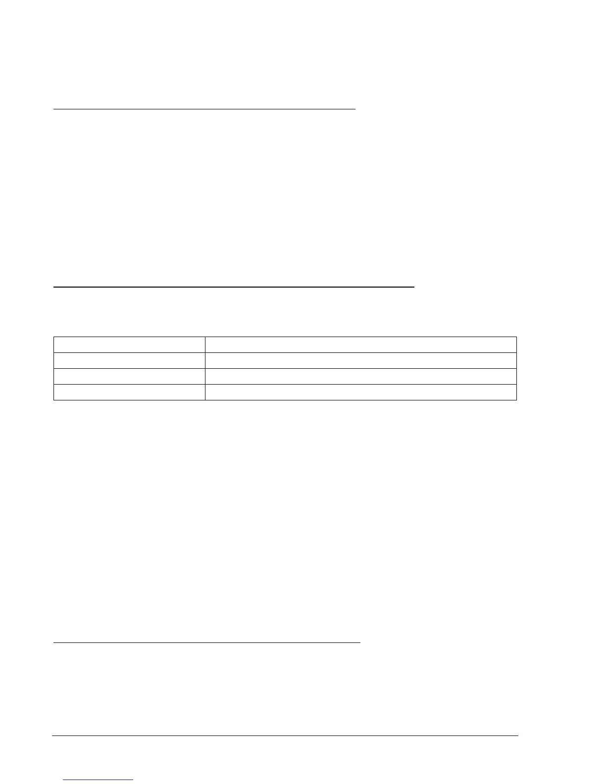
Table 13-36 as a guide, transmit the 67 setting commands to the relay.
Table 13-36. 67P-50TQ Operational Settings
Operating Settings Purpose
S0-50TP=0,0,F Sets 50TP at 0 amps, 0 Time Delay, Forward Tripping Direction.
S0-50TN=0,0,F Sets 50TN at 0 amps, 0 Time Delay, Forward Tripping Direction.
S0-50TQ=0.5,0,F Sets 50TQ at 0.5 amps, 0 Time Delay, Forward Tripping Direction.
Step 10: Apply a 120 Vac, three-phase voltage source at nominal frequency to Terminals C13 (A-phase),
C14 (B-phase), C15 (C-phase), and C16 (Neutral). Reduce the A-phase voltage by 1/3.
Transmit M-V command or view HMI Screen 3.4 to verify that negative-sequence voltage is
greater than 1 volt.
Step 11: Apply 0 amp A-phase current at an angle of 80 degrees I lag E (same as positive-sequence line
angle) and slowly increase the current until OUT3 closes (Negative-Sequence Pickup current
will be approximately the applied A-phase current value). Decrease A-phase current until OUT3
just drops out. Pickup will occur within ±2 percent of the 50TQ pickup setting. Dropout will occur
at 93 to 97% of actual pickup. Verify the 67Q target on the HMI.
Step 12: With the same voltage still applied, increase the A-phase current until OUT3 closes. Swing the
angle of the applied current +90 degrees and -90 degrees away from the 80-degree positive-
sequence line angle. Verify that OUT3 opens at approximately 170 degrees I lag E and 350
degrees I lag E. OUT3 should remain closed from 170 through 80 to 350 degrees I lag E
(defined as forward trip direction)
Step 13: (Optional.) Repeat Steps 3 through 12 for B-phase current (D3 and D4) and C-phase current
(D5 and D6). Reduce the corresponding B-phase and C-phase voltage for negative-sequence
tests.
Negative-Sequence Voltage Polarizing, Ground Overcurrent Elements
Step 14: Using
Table 13-37 as a guide, transmit the 67 setting commands to the relay.