9328900990 Rev L BE1-951 Testing and Maintenance 13-31
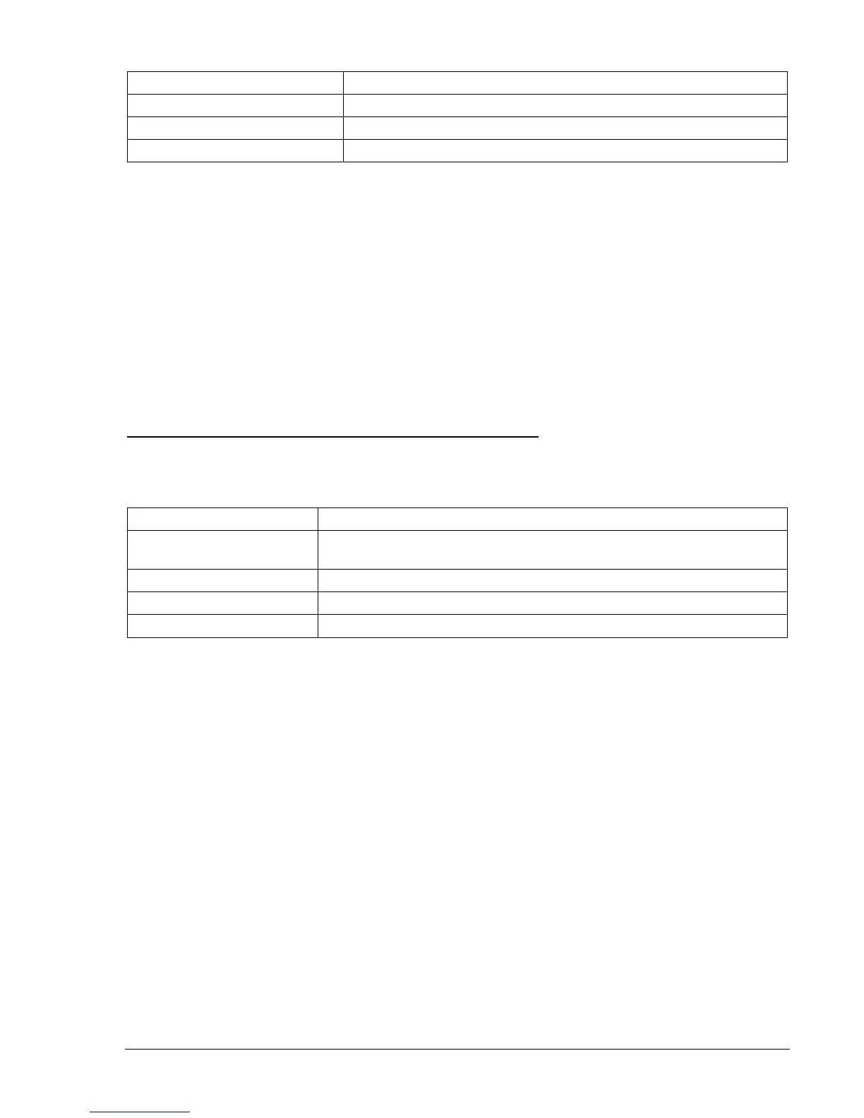
Table 13-37. 67N (Q pol)-50TN Operational Settings
Operating Settings Purpose
S0-50TP=0,0,F Sets 50TP at 0 amps, 0 Time Delay, Forward Tripping Direction.
S0-50TN=2.0,0,F Sets 50TN at 2.0 amps, 0 Time Delay, Forward Tripping Direction.
S0-50TQ=0,0,F Sets 50TQ at 0 amps, 0 Time Delay, Forward Tripping Direction.
Step 15: Apply a 120 Vac, three-phase voltage source at nominal frequency to Terminals C13 (A-phase),
C14 (B-phase), C15 (C-phase), and C16 (Neutral). Reduce the A-phase voltage by 1/3.
Transmit M-V command or view HMI Screen 3.4 to verify that negative-sequence voltage is
greater than 1 volt.
Step 16: Apply 0 amp A-phase current at an angle of 80 degrees I lag E (same as positive-sequence line
angle) and slowly increase the current until OUT2 closes. Decrease A-phase current until OUT2
just drops out. Pickup will occur within ±2 percent of the 50TN pickup setting. Dropout will occur
at 93 to 97% of actual pickup. Verify the 67N target on the HMI.
Step 17: With the same voltage still applied, increase the A-phase current until OUT2 closes. Swing the
angle of the applied current +90 degrees and -90 degrees away from the 80-degree positive-
sequence line angle. Verify that OUT2 opens at approximately 170 degrees I lag E and 350
degrees I lag E. OUT2 should remain closed from 170 through 80 to 350 degrees I lag E
(defined as forward trip direction)
Zero-Sequence Voltage Polarizing, Ground Overcurrent Elements
Step 18: Using
Table 13-38 as a guide, transmit the 67 setting commands to the relay.
Table 13-38. 67N (V0 pol)-50TN Operational Settings
Operating Settings Purpose
S0-67=V,VOIN
Sets 67N to Zero-Sequence Voltage Polarizing. V0IN compares
calculated V0 to calculated 3I0 (IN).
S0-50TP=0,0,F Sets 50TP at 0 amps, 0 Time Delay, Forward Tripping Direction.
S0-50TN=2.0,0,F Sets 50TN at 2.0 amps, 0 Time Delay, Forward Tripping Direction.
S0-50TQ=0,0,F Sets 50TQ at 0 amps, 0 Time Delay, Forward Tripping Direction.
Step 19: Apply a 120 Vac, three-phase voltage source at nominal frequency to Terminals C13 (A-phase),
C14 (B-phase), C15 (C-phase), and C16 (Neutral). Reduce the A-phase voltage by1/3. Transmit
M-V command or view HMI Screen 3.4 to verify that the zero-sequence voltage is greater than 1
volt.
Step 20: Apply 0 amp A-phase current at an angle of 80 degrees I lag E (zero-sequence line angle) and
slowly increase the current until OUT2 closes. Decrease A-phase current until OUT2 just drops
out. Pickup will occur within ±2 percent of the 50TN (calculated 3I0) pickup setting. Dropout will
occur at 93% to 97% of actual pickup. Verify the 67N target on the HMI.
Step 21: With the same voltage still applied, increase the A-phase current until OUT2 closes. Swing the
angle of the applied current +90 degrees and -90 degrees away from the 80 degree zero-
sequence line angle. Verify that OUT2 opens at approximately 170 degrees I lag E and 350
degrees I lag E. OUT2 should remain closed from 170 through 80 to 350 degrees I lag E
(defined as forward trip direction). Steps 18 through 21 verify polarizing reference quantities
V0IN with 50TN set to operate for IN (calculated 3I0) as per
Table 13-34 (SL-50TN=1,0). The
50TN element can also be set to operate for measured ground current IG (optional IG input)
while still being polarized by V0IN. To verify, connect A-phase current in series with IG current.
That is, polarity current should go in D1 out D2, in D7 out D8. Repeat Steps 19 through 21 with
50TN set for IG operate (SL-50TN=2, 0). Verify the 67G target on the HMI.
Step 22: Transmit S0-67=V,V0IG. The polarizing reference quantities are V0 compared to IG measured.
This compares calculated V0 to measured IG (independent ground input). Repeat Steps 19
through 21 with A-phase current connected in series with IG current. That is, polarity current
should go in D1 out D2, in D7 out D8. Verify the 67G target on the HMI. Note that 50TN can