13-32 BE1-951 Testing and Maintenance 9328900990 Rev L
also be set to operate for calculated IN (3I0) while still being polarized by V0IG. Verify operation
by repeating Steps 19 through 21 with 50TN set for IN operate (SL-50TN=1, 0). Verify the 67N
target on the HMI.
Step 23: Transmit S0-67=V, VXIG and set SL-50TN=2,0. The polarizing reference quantities are an
external source of 3V0 applied at the VX input compared to measured IG (independent ground
input). Apply polarity of a single-phase voltage source (30 Vac at nominal frequency) to
Terminal C17 and non-polarity to C18 at an angle of 180 degrees I lag E. An angle of 180
degrees is used to simulate a broken delta voltage where polarity to non-polarity is 180 degrees
out of phase with, for example, the A-phase current during an A-phase to ground fault. The
relay internally compensates for the 180 degree phase difference such that polarity voltage from
the broken delta source connected to polarity of the relay results in a 0 degree condition for a
Forward fault. To verify, connect A-phase current in series with IG current. That is, polarity
current should go in D1 out D2, in D7 out D8. Repeat Steps 20 and 21 with 50TN set for IG
operate (SL-50TN=2,0). Verify the 67G target on the HMI. Note that 50TN can also be set to
operate for calculated IN (3I0) while still being polarized by VXIG. Verify operation by repeating
Steps 20 and 21 with 50TN set for IN operate (SL-50TN=1,0). Verify the 67N target on the HMI.
Step 24: Transmit S0-67=V,VXIN. The polarizing reference quantities are an external source of 3V0
applied at the VX input compared to the calculated IN (3I0) quantity. Apply polarity of a single-
phase voltage source (30 Vac at nominal frequency) to Terminal C17 and non-polarity to C18 at
an angle of 180 degrees I lag E. An angle of 180 degrees is used to simulate a broken delta
voltage where polarity to non-polarity is 180 degrees out of phase with, for example, the A-
phase current during an A-phase to ground fault. The relay internally compensates for the 180
degree phase difference such that polarity voltage from the broken delta source connected to
polarity of the relay results in a 0 degree condition for a Forward fault. To verify, connect A-
phase current in series with IG current (if this option is available). That is, polarity current should
go in D1 out D2 and in D7 out D8 if IG option is available. Repeat Steps 20 and 21 with 50TN
set for IN operate (SL-50TN=1, 0). Verify the 67N target on the HMI. Note that 50TN can also
be set to operate for measured independent ground (IG) while still being polarized by VXIN.
Verify operation by repeating Steps 20 and 21 with 50TN set for IN operate (SL-50TN=1, 0).
Verify the 67N target on the HMI.
Step 25: Repeat Steps 3 through 24 for "Reverse Polarization." Relay operation will occur 180 degrees
away from the Positive and Negative-Sequence line angle (both at 80 degrees or 260 degrees I
lags E in our example). Verify that the output contacts remain closed from 170 through 260 to
350 degrees I lags E.
Step 26: (Optional.) Repeat Steps 3 through 25 for 150TNQ, 51TNQ, and 151N. Setup commands and
associated operational setting tables must be modified accordingly, i.e., all "50" entries would
change to "150," and so on.
Step 27: (Optional.) Repeat Steps 3 through 25 for Setting Groups 1, 2, and 3.
Zero-Sequence Current Polarization
Step 1: Use setup commands in
Table 13-34. Using Table 13-39 as a guide, transmit the 67 setting
commands to the relay.
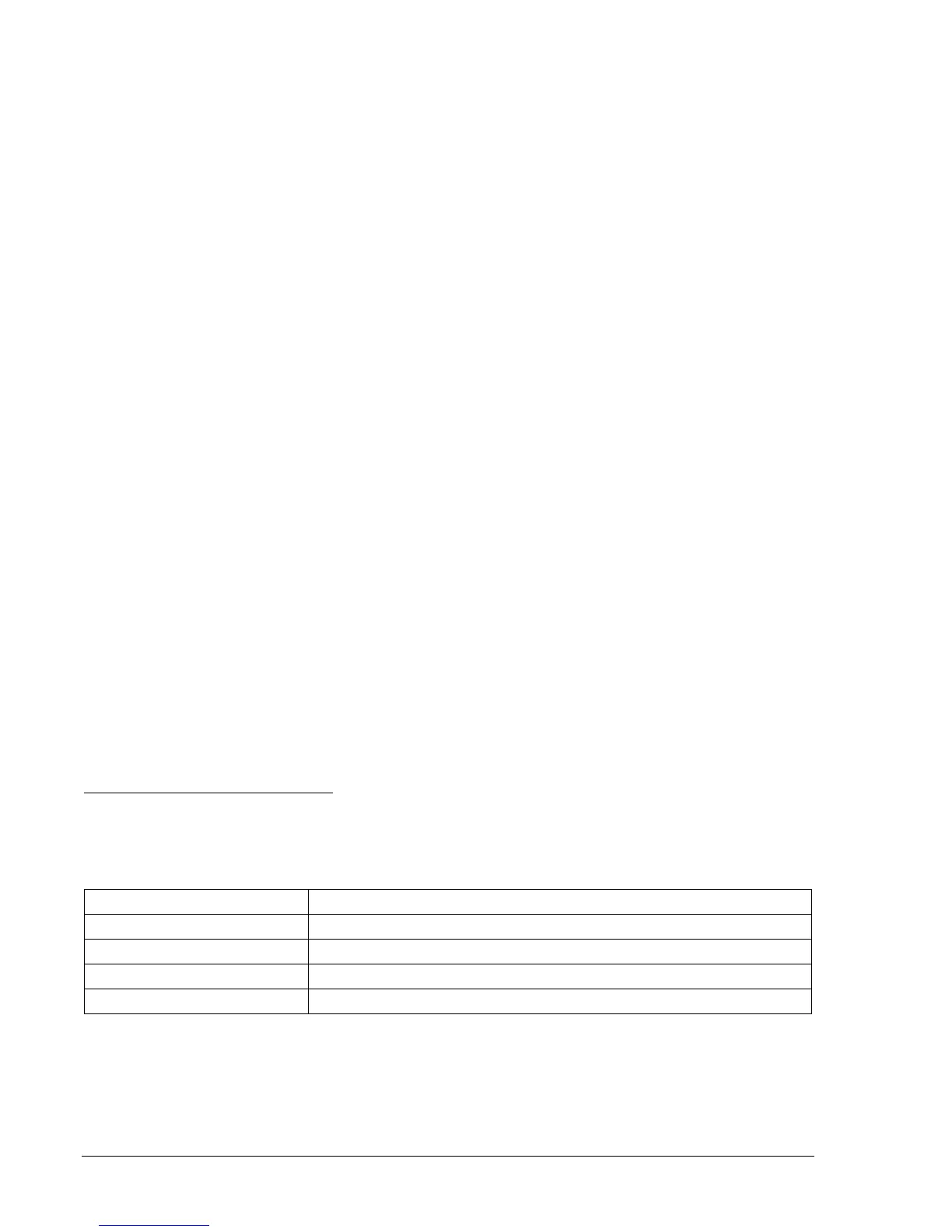
Table 13-39. 67N (Io pol)-50TN Operational Settings
Operating Settings Purpose
S0-67=I Sets 67N to Zero-Sequence Current Polarizing.
S0-50TP=0,0,F Sets 50TP at 0 amps, 0 Time Delay, Forward Tripping Direction.
S0-50TN=2.0,0,F Sets 50TN at 2.0 amps, 0 Time Delay, Forward Tripping Direction.
S0-50TQ=0,0,F Sets 50TN at 0 amps, 0 Time Delay, Forward Tripping Direction.
Step 2: Apply 2 amps ac current at 0 degrees to the independent ground input IG, Terminals D7
(polarity) and D8 (non-polarity). No ac voltage is required for this test.
Step 3: From a second current source, apply 0 amp A-phase current at an angle of 0 degrees and
slowly increase the current until OUT2 closes. Decrease A-phase current until OUT2 just drops