9328900990 Rev L BE1-951 Testing and Maintenance 13-39
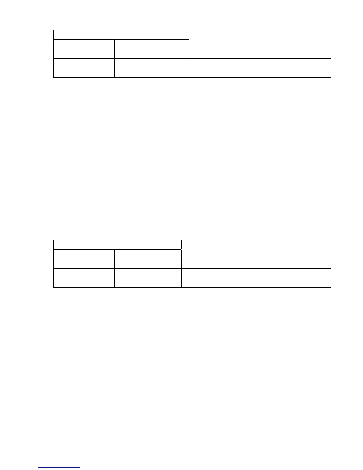
Table 13-53. 27X and 59X/159X Pickup Settings (3E0)
Pickup Settings
Undervoltage Overvoltage
Purpose
S0-27X=50,50ms S0-59X/159X=60,50ms Sets 27X PU at 50 V, 59X/159X at 60 V, TD at min.
S0-27X=20,50ms S0-59X/159X=30,50ms Sets 27X PU at 20 V, 59X/159X at 30 V, TD at min.
S0-27X=5,50ms S0-59X/159X=10,50ms Sets 27X PU at 5 V, 59X/159X at 10 V, TD at min.
Step 3: Prepare to monitor the 59X/159X function operation. Operation can be verified by monitoring
OUT1 (OUT2 for 159X).
Step 4: Connect and apply a single-phase, 55 Vac voltage source to Terminals C13 (polarity) and C16
(non-polarity). Refer to
Figure 13-1 for terminal locations.
Step 5: Slowly decrease the voltage until OUT1 closes. Pickup should occur within ±2 percent or 1 volt
of the 27X pickup setting. Slowly increase the voltage until OUT1 opens. Dropout should occur
between 102 and 103 percent of the actual pickup value. Verify the 27NTarget on the HMI and
reset.
Step 6: Continue increasing the voltage until OUT1 closes. Pickup should occur within ±2 percent or 1
volt of the pickup setting. Slowly reduce the voltage until OUT1 opens. Dropout should occur
between 97 and 98 percent of the actual pickup value. Verify the 59N Target on the HMI.
Step 7: Verify the pickup and dropout accuracy of the middle and upper pickup settings in
Table 13-53.
Step 8: (Optional.) Repeat Steps 2 through 7 for the B-phase and C-phase voltage inputs.
Step 9: (Optional.) Repeat Steps 2 through 8 for Setting Groups 1, 2, and 3.
Auxiliary Undervoltage/Overvoltage Timing Verification (3E0 VT Input)
Step 1: Using
Table 13-54 as a guide, transmit the first row of setting commands to the relay.
Table 13-54. 27X and 59X/159X Pickup and Time Delay Settings (3E0 VT Input)
Pickup Settings
Undervoltage Overvoltage
Purpose
S0-27X=10,2S S0-59X/159X=30,2S Sets 27X PU at 10 V, 59X/159X at 30 V, TD at 2 sec.
S0-27X=,5S S0-59X/159X=,5S Sets 27X PU at 10 V, 59X/159X at 30 V, TD at 5 sec.
S0-27X=,10S S0-59X/159X=,10S Sets 27X PU at 10 V, 59X/159X at 30 V, TD at 10 sec.
Step 2: Prepare to monitor the 27X and 59X/159X timings. Timing accuracy is verified by measuring the
elapsed time between a sensing voltage change and OUT1 closing.
Step 3: Connect and apply a single-phase, 20 Vac to Terminals C13 (polarity) and C16 (non-polarity).
Refer to
Figure 13-1 for terminal locations.
Step 4: Step the voltage down to 5 volts. Measure the time delay and verify the accuracy of the 27X
time delay setting. Timing accuracy is ±0.5 percent or ±1 cycles of the time delay setting.
Step 5: Step the voltage up to 35 volts. Measure the time delay and verify the accuracy of the 59X/159X
time delay setting. Timing accuracy is ±0.5 percent or ±1 cycles of the time delay setting.
Step 6: Repeat Steps 5 and 6 for the middle and upper time delay settings of
Table 13-54.
Step 7: (Optional.) Repeat Steps 2 through 6 for Setting Groups 1, 2, and 3.
Auxiliary Undervoltage/Overvoltage Pickup Verification (Fundamental Vx Input)
Step 1: Prepare the 27X and 59X/159X pickup functions for testing by transmitting the commands in
Table 13-55 to the relay. Reset targets.