13-40 BE1-951 Testing and Maintenance 9328900990 Rev L
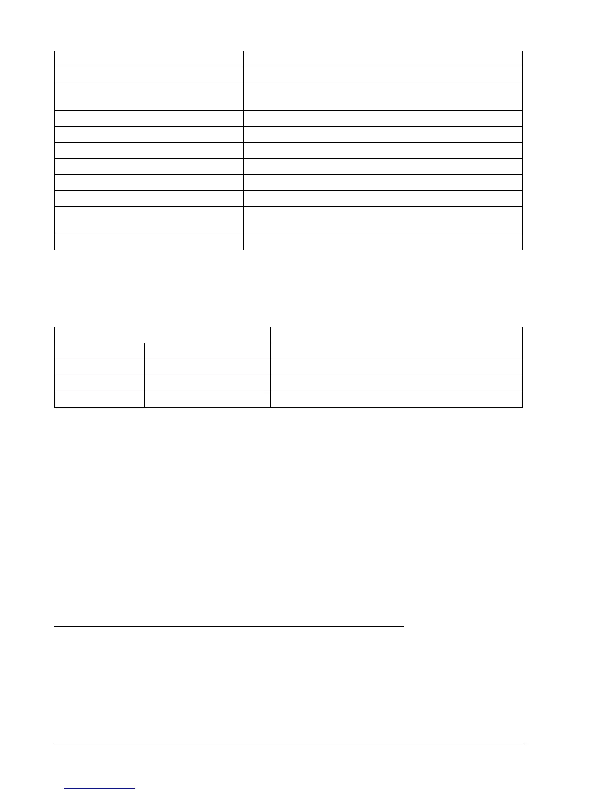
Table 13-55. 27X and 59X/159X Pickup Test Commands
Command Purpose
A= Gains write access.
SL-N=NONE
Zero out custom logic settings. Overwrite with
LOGIC=NONE settings.
Y Confirm overwrite.
SL-N=27X_59X/159X Sets 27X_59X/159X as custom logic name.
SG-VTX=1,AN Set auxiliary voltage parameters.
SL-27X=1,0 Enables 27X, disables blocking.
SL-59X/159X=1,0 Enables 59X and 159X, disables blocking.
SL-VO1=27XT+59XT+159XT Enables OUT1 to close for 27X, 59X, or 159X trip.
SG-TRIG=27XT+59XT+159XT,
27XPU+59XPU+159XPU
Enables 27XT, 59XT, or 159XT to log and trigger fault
recording.
EXIT;Y Exit and save settings.
Step 2: Using
Table 13-56 as a guide, transmit the first row of setting commands (highest 27X PU;
lowest 59XPU/159XPU) to the relay.
Table 13-56. 27X and 59X/159X Pickup Settings
Pickup and Time Delay Settings
Undervoltage Overvoltage
Purpose
S0-27X=70,50ms S0-59X/159X=90,50ms Sets 27X PU at 70 V, 59X/159X at 90 V, TD at min.
S0-27X=60,50ms S0-59X/159X=100,50ms Sets 27X PU at 60 V, 59X/159X at 100 V, TD at min.
S0-27X=50,50ms S0-59X159X=110,50ms Sets 27X PU at 50 V, 59X/159X at 110 V, TD at min.
Step 3: Prepare to monitor the 27X and 59X/159X function operation. Operation can be verified by
monitoring OUT1.
Step 4: Connect and apply a single-phase, 80 Vac voltage source to VX input, Terminals C17 (polarity)
and C18 (non-polarity). Refer to
Figure 13-1 for terminal locations.
Step 5: Slowly decrease the voltage until OUT1 closes. Pickup should occur within ±2 percent or 1 volt
of the pickup setting. Slowly increase the voltage until OUT1 opens. Dropout should occur
between 102 and 103 percent of the actual pickup value. Verify the 27 bus target on the HMI
and reset.
Step 6: Continue to increase the voltage until out1 closes. Pickup should occur within ±2 percent or 1
volt of the pickup setting. Slowly reduce the voltage until OUT1 opens. Dropout should occur
between 97 and 98 percent of the actual pickup value. Verify the 59 bus target on the HMI.
Step 7: Verify the pickup and dropout accuracy of the middle and upper pickup settings listed in
Table
13-56.
Step 8: (Optional.) Repeat Steps 2 through 7 for Setting Groups 1, 2, and 3.
Auxiliary Undervoltage/Overvoltage Timing Verification (Fundamental Vx Input)
Step 1: Using
Table 13-57 as a guide, transmit the first row of setting commands to the relay.