9328900990 Rev L BE1-951 Testing and Maintenance 13-51
Mode 2 - On/Off
Step 1: Prepare for Mode 2 testing by transmitting the commands in
Table 13-79 to the relay.
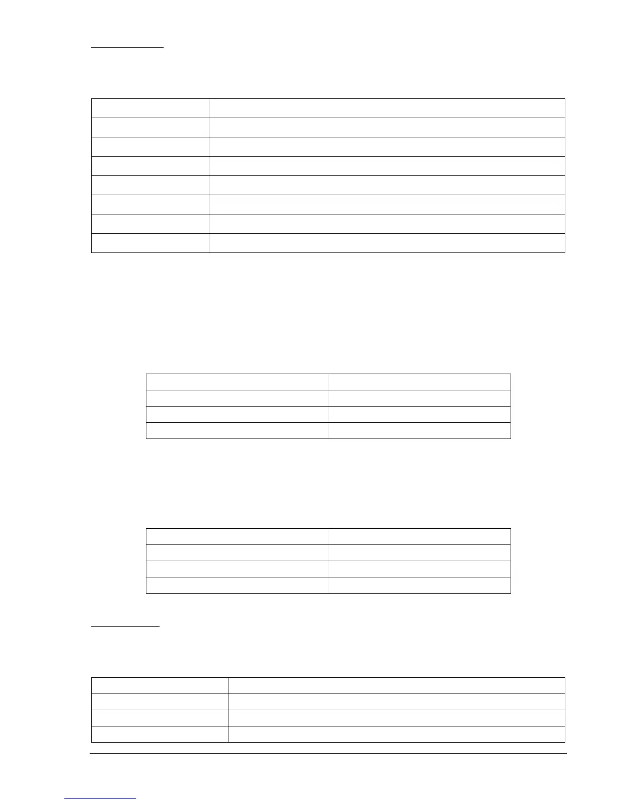
Table 13-79. x43 Mode 2 Test Commands
Command Purpose
A= Gains write access.
SL-N=NONE Zero out custom logic settings. Overwrite with LOGIC=NONE settings.
Y Confirm overwrite.
SL-N=MODE2 Sets MODE2 as custom logic name.
SL-143=2 Sets 143 Switch for Mode 2 operation.
SL-VO1=143 Enables OUT1 to close for 143.
EXIT;Y Exit and save setting
Step 2: Prepare to monitor the virtual switch operation. An ohmmeter or continuity tester may be used
to monitor the contact status of OUT1.
Step 3: Transmit the commands in
Table 13-80 to the relay. These commands change the state of the
43 Switch to On.
Result: OUT1 contact closes and remains closed.
Table 13-80. x43 Mode 2 On Commands
Command Purpose
A= Gains write access.
CS-143=1 Selects 143 for On operation.
CO-143=1 Executes 143 for On operation.
Step 4: Transmit the commands in
Table 13-81 to the relay. These commands change the state of the
143 Switch to Off. It isn't necessary to gain access for the following steps unless the write
access timer expires.
Table 13-81. x43 Mode 2 Off Commands
Command Purpose
A= Gains write access.
CS-143=0 Selects 143 for Off operation.
CO-143=0 Executes 143 for Off operation.
Mode 3 - Pulse
Step 1: Prepare for Mode 3 testing by transmitting the commands in
Table 13-82 to the relay.
Table 13-82. x43 Mode 3 Test Commands
Command Purpose
A= Gains write access.
SL-N=NONE Zero out custom logic settings. Overwrite with LOGIC=NONE settings.
Y Confirm overwrite.