9328900990 Rev L BE1-951 Testing and Maintenance 13-53
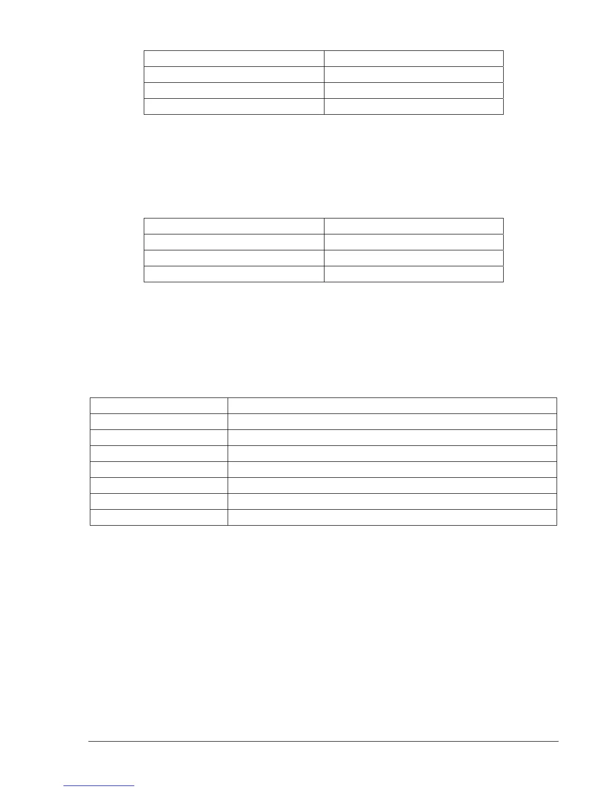
Table 13-85. 101 Virtual Breaker Control Switch Trip Test Commands
Command Purpose
A= Gains write access.
CS-101=T Selects 101T for Trip operation.
CO-101=T Executes 101T for Trip operation.
Step 4: Transmit the commands in
Table 13-86 to the relay. These commands place the 101 Switch in
the closed state.
Result: OUT2 closes for 200 milliseconds and returns to the open state. OUT3 closes (close
state) and remains closed.
Table 13-86. 101 Virtual Breaker Control Switch Close Test Commands
Command Purpose
A= Gains write access.
CS-101=C Selects 101C for Close operation.
CO-101=C Executes 101C for Close operation.
Virtual Lockout (86)
Purpose: To verify 86, 186 Virtual Lockout operation.
Reference Commands: SL-86, SL-186
Step 1: Prepare the 86 Virtual Lockout for testing by transmitting the commands in
Table 13-87 to the
relay.
Table 13-87. 86 and 186 Virtual Lockout Test Commands
Command Purpose
A= Gains write access.
SL-N=NONE Zero out custom logic settings. Overwrite with LOGIC=NONE settings.
Y Confirm overwrite.
SL-N=LO_86 Set LO_86 as custom logic name.
SL-86=1,IN1,IN2 Enables 86 lockout latch, IN1 = Trip, IN2 = Reset.
SL-VO1=86 Enables OUT1 to close when 86 is TRUE.
EXIT;Y Exit and save settings.
Step 2: Prepare to monitor the 86 virtual lockout operations. Operation can be verified by monitoring
OUT1 at HMI Screen 1.5.2, or monitoring OUT1 contacts between Terminals C1 and C2 or by
using the RG-STAT command. See Section 6, Reporting and Alarm Functions, for more
information.
Step 3: Connect negative or non-polarity power supply voltage (PSV) to Input 1 and 2 Terminals B2 and
B4.
Step 4: Apply and remove positive or polarity PSV to Input1, Terminal B1. Verify that OUT1 closes and
remains closed.
Step 5: Power down the relay and verify that OUT1 opens. Wait 10 seconds and power up the relay.
Verify that OUT1 closes. This verifies that the 86 position is stored in nonvolatile memory.
Step 6: Apply and remove positive or polarity PSV to Input2, Terminal B3. Verify that OUT1 opens and
remains open.
Step 7: Repeat Steps 1 through 6 for the 186 Virtual Lockout.