9328900990 Rev L BE1-951 BESTCOMS Software 14-7
Power System
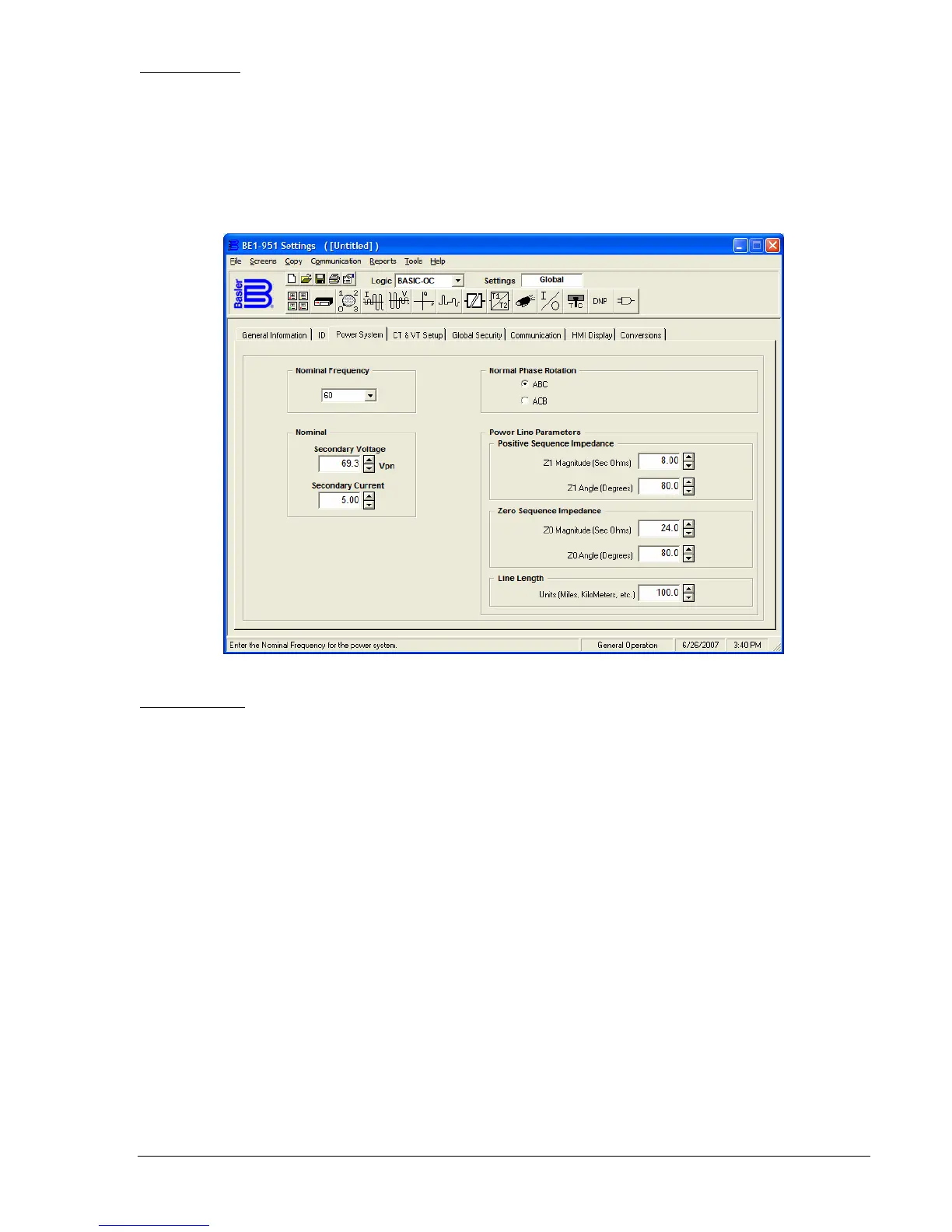
This tab (
Figure 14-7) allows you to enter the frequency, phase rotation, nominal CT secondary voltage,
and current and power line parameters. If the phase rotation entry is not correct, it will cause problems in
several areas including metering values and targets. Power line parameters are necessary for line
protection. In other words, you must make entries in these fields in order for the BE1-951 protection
elements to function. These symmetrical component sequence quantities are entered to provide
immediate reference information for settings of the protection elements in the BE1-951 relay. Distance to
fault calculation accuracy is also dependent on the power line parameters entered in this screen.
Figure 14-7. General Operation Screen, Power System Tab
CT & VT Setup
This tab (
Figure 14-8) allows you to enter the CT ratios and setup the VT parameters. These entries affect
every function that relies on voltage and current measurements and calculations derived from those
measurements. Pull down the CT Ratio, Phase, Sec Amps menu and select the appropriate secondary
nominal current input. Enter the CT Ratio, Phase, and Turns value and the primary amperes value is
entered for you. For example, if you entered 240 for the Turns value and the secondary nominal current
input is 1, the primary amperes value is 240. If you change the secondary nominal current input to 5, the
primary amperes value becomes 1,200. If the ground current input is valid for your relay, enter the
appropriate values
The VTP Setup is very similar. You may click once in an entry window and select the entire value
entered. If you are making an entry in the window, clicking once locates the cursor in the entry and
clicking twice selects the entire value entered. Over/undervoltage modes can be set to operate on either
the phase-to-neutral (PN) or phase-to-phase (PP) quantities. Click on the appropriate button to select the
quantity required. Pull down the connection menu and select the appropriate connection for phase
voltage input. Perform these same steps for the VTX Setup if the auxiliary voltage input is valid.