Wiring diagram
file:///D|/Manuales/Para%20recolocar/MOTOS/DUCATI/DUCATI/M796/wsm/EN/M796_ABS_11_6_1A.24.1.html[11/12/2015 18:40:18]
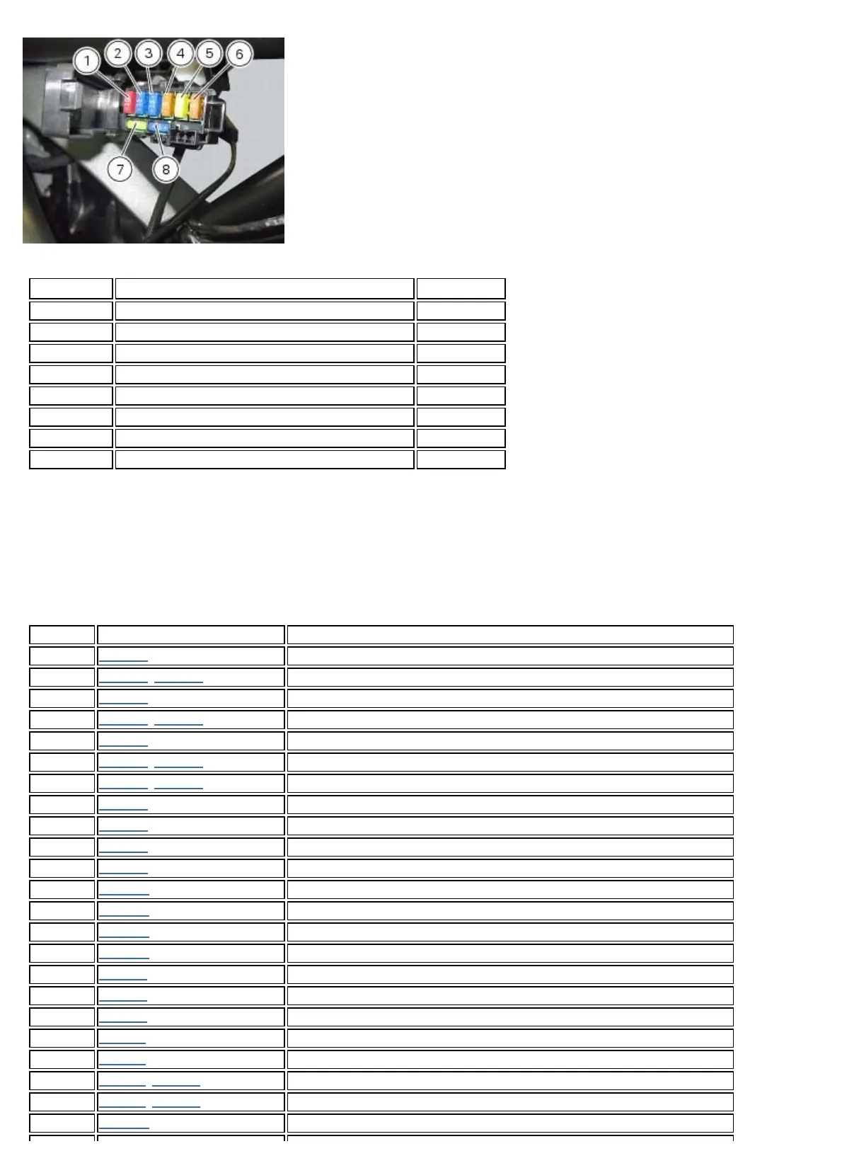
Position Consumer Rating
1 Key ON 10 A
2 Side lights, high/low beam 15 A
3 El. item 15 A
4 Instrument panel 5 A
5 Injection 20 A
6 ECU 5 A
7 Spare 20 A
8 Spare 15 A
Routing of wiring on frame
The routing of the wiring has been optimised to ensure the minimum obstruction.
Each section is designed to prevent interference with parts that might damage wires or cause operating failures when
riding. The plates on the following pages show the origins (“0” points) for correct re-routing of wiring and the locations of
cable ties.
Each figure includes references to the plates showing the wiring routing or the item to which it must be connected.
Position Description
1
Table A Main wiring branch
2
Table B/Table C Left-hand handlebar switch connector
3
Table B Clutch connector
4
Table B/Table C Clutch wire
5
Table B Front brake light connector
6
Table B/Table C Right-hand handlebar switch connector
7
Table B/Table C Front brake light wire
8
Table B Immobilizer antenna connector
9
Table B Key switch connector
10
Table B Immobilizer antenna wire
11
Table B Key-switch
12
Table D Front right turn signal connector
13
Table D Front left turn signal connector
14
Table D Headlight connector
15
Table D Instrument panel connector
16
Table E Vertical cylinder injector connector
17
Table E Air/temperature sensor
18
Table E Horizontal cylinder injector connector
19
Table F Engine earth
20
Table F Side stand connector
21
Table F/Table P Battery negative terminal
22
Table F/Table P Side stand wire
23
Table H Alternator cable