Operating manual.
CNC 8060
CNC 8065
JOG MODE. PART CENTERING (MILL MODEL)
7.
Data programming.
·149·
(REF: 1807)
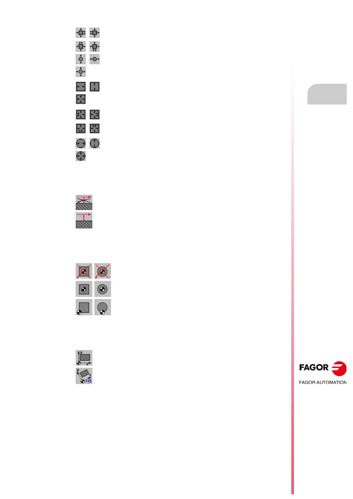
·icon· Surface coordinate measuring.
This parameter indicates whether the cycle must also measure the position of the top surface
of the part.
·icon·Preset the part zero after ending the cycle.
This parameter indicates whether the part zero is to be preset or not, if so, the point taken
as reference. This point may be preset with any value using parameters ·Px Py Pz·.
·icon·Pattern rotation.
For rectangular parts, this parameter indicates whether a coordinate rotation is to be applied
or not with the measured angle.
·Lx Ly Ø·Part dimensions.
These parameters establish the dimensions of the rectangular or circular part.
For a rectangular part, parameters ·Lx· and ·Ly· indicate the length of the pocket on each
axis. The sign indicates tool orientation.
Rectangular part. Center the part on both axes, with two probings on the first side.
Circular part. Center the part on one axis.
Circular part. Center the part on both axes, with one probing on the first side.
Rectangular pocket. Center the pocket on one axis.
Rectangular pocket. Center the pocket on both axes, with one probing on the first
side.
Rectangular pocket. Center the pocket on both axes, with two probings on the
first side.
Circular pocket. Center the pocket on one axis.
Circular pocket. Center the pocket on both axes, with one probing on the first side.
The cycle does not measure the surface coordinate.
The cycle measures the surface coordinate.
Do not preset the part zero.
Preset the part zero at the center of the part.
Preset the part zero at one of the corners (the cycle shows an icon for each
corner).
Do not rotate the coordinates (pattern).
Rotate the coordinates (pattern).
Lx Rectangular part. Part length along the abscissa axis.
Ly Rectangular part. Part length along the ordinate axis.
Ø Circular part. Part diameter.
 Loading...


