3. Mode
35220
8/9
35220
Maintenance
Input Check (Processor) [J]
Description for each specification
For the specifications other than [F] specification, this section only gives description that differs from that for [F] specification. See below
for the description for each specification.
!
!!
! 1 [J]
!
!!
! 2 [J]
*1. Displays OK if all circulation pumps are normally rotating.
When an error occurs, displays the circulation pump at which an error is occurring. (CD, BF, STB1, STB2, STB3, STB4)
If the errors occur at two or more pumps simultaneously, the error is displayed in the order from CD.
*2. Displays only when the digital flowmeter is registered as options.
*3. It may take one minute for communicating between the processor control PCB and control strip unit.
!
!!
! Tablet Replenishment Section [J]
Reference
☞Input Check (Processor) [N] ☞Input Check (Processor) [SM] ☞Input Check (Processor) [F]
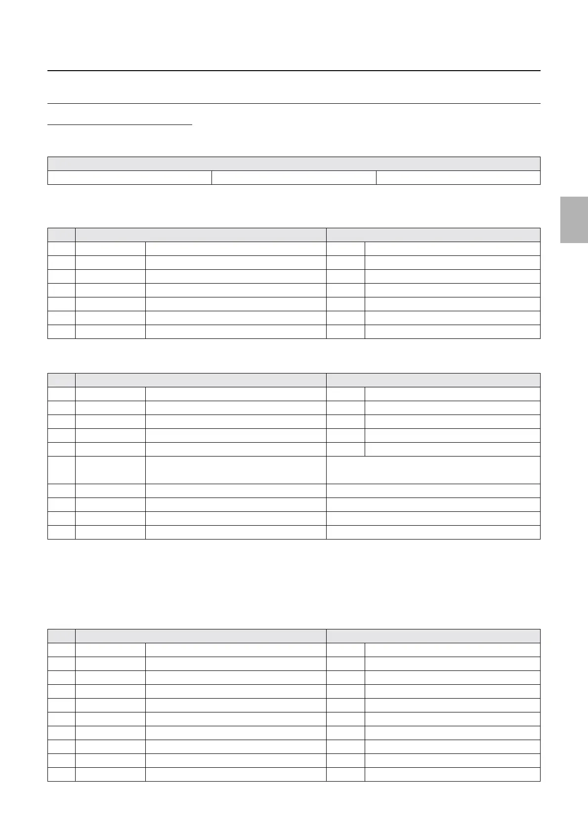
No. Display Status
1 ON/OFF Processing Solution Level OFF When the solution level is too low.
2 ON/OFF SW Tank Level Sensor OFF When the solution level is too low.
3 ON/OFF SW/DW Tank Level Sensor OFF When the solution level is too low.
4 ON/OFF STB 1 Refilling Water Level OFF When the solution level is too low.
5 ON/OFF Processing Solution Safety Thermostat ON Normal
6 ON/OFF Interlock Switch (Processor Top Cover) ON When the cover is closed.
7 ON/OFF Rack Stopper Sensor ON When the rack stopper is set.
No. Display Status
1 ON/OFF CD Effluent Float Switch ON When the effluent is full.
2 ON/OFF BF Effluent Float Switch ON When the effluent is full.
3 ON/OFF STB Effluent Float Switch ON When the effluent is full.
4 CLOSE/OPEN Starter Jumper Setting CLOSE When the jumper of power PCB 2 is connected.
5 ON/OFF Control strip holder detection switch
*3
ON When the control strip holder is detected
6 ON/OFF Control strip processing complete.
*3
• ON: Advancing the control strip is completed.
• OFF: Advancing the control strip is not completed.
7 ### Pump Rotation Detector When an error occurs.
*1
8 50/60 Power Supply Frequency (Hz) Displays the frequency.
9 #.## CD Flow Amount Displays the CD circulation amount.
*2
10 ### Drive Motor Revolution Count
No. Display Status
1 DARK/LIGHT CD Tablet Sensor 1 DARK When the tablet is detected
2 DARK/LIGHT CD Tablet Sensor 2 DARK When the tablet is detected
3 DARK/LIGHT BF Tablet Sensor 1 DARK When the tablet is detected
4 DARK/LIGHT BF Tablet Sensor 2 DARK When the tablet is detected
5 DARK/LIGHT STB Tablet Sensor 1 DARK When the tablet is detected
6 DARK/LIGHT STB Tablet Sensor 2 DARK When the tablet is detected
7 DARK/LIGHT CD Cartridge Sensor LIGHT When the cartridge is detected
8 DARK/LIGHT BF Cartridge Sensor LIGHT When the cartridge is detected
9 DARK/LIGHT STB Cartridge Sensor LIGHT When the cartridge is detected
10 DARK/LIGHT Elevator Upper Sensor DARK When the elevator is detected
Distributed by: minilablaser.com