Data flow
1/1
5. Operation sequence
50700
50700
Data flo w
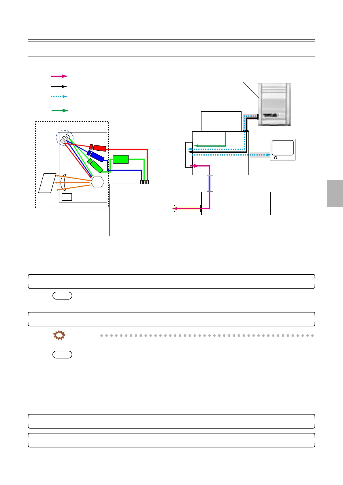
Data flow in printing
!
!!
! Input of this system operation is film scanning operation and output is printing
operation.
1. When input is film, scan the film in the scanner unit.
NOTE
• The scanner unit corrects the gap in the sub-scanning direction (pixel gap of CCD of RGB).
2. The image is processed with the EZ Controller.
IMPORTANT
• Scratch erasing is performed by DIGITAL ICE Technology Correction.
NOTE
• Image correction of actual scanning data such as color and density correction, DSA, and image rotation are performed on
with the EZ Controller.
• Image data editing such as frame combination, front print combination and paper fitting is performed with the EZ
Controller.
• The pre-scanned data of the scanner is transferred to the EZ Controller and displayed on the PJP monitor and printed on
index prints.
• The data sent from a media drive as well as the processing method of data of coming from a film is printed via the HDD.
3. The image data is output to the laser engine through the printer I/F main PCB → laser control PCB.
4. The laser engine exposes the paper.
B laser
G laser
R laser
G-AOM
driver
HDD
ATX MOTHER
BORD
LVPECL
USB
LAN
Actual scanning data
Prescanning data
Print data
Data coming from the media drive
AFC/scanner control PCB
Laser control PCB
Laser unit
Media drive
Printer I/F main PCB
G085221
Distributed by: minilablaser.com