Explanation of PCBs (Processor section)
1/1
6. Electrical parts
66870
66870
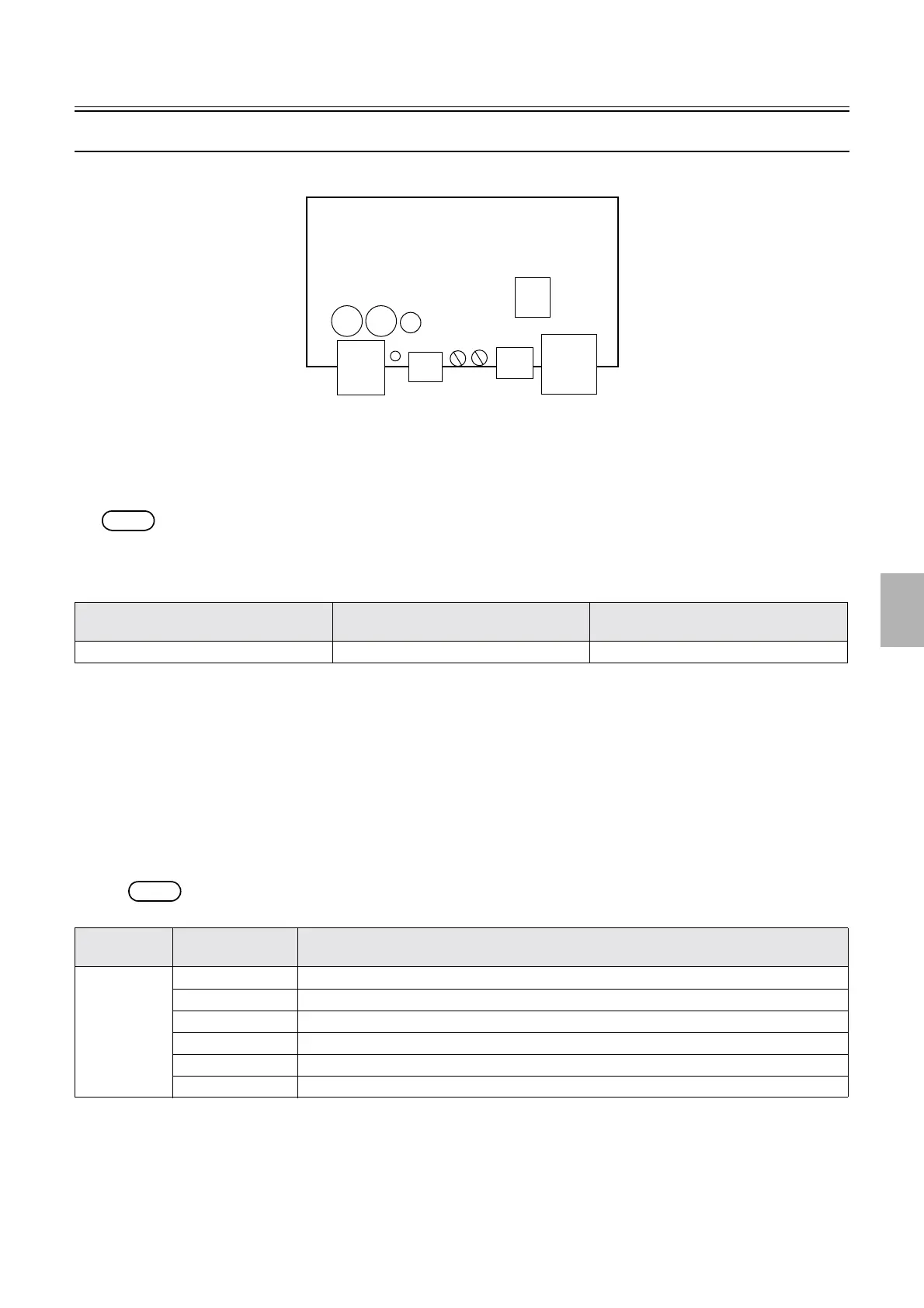
Drive motor driver PCB (I123279)
!
!!
! Function
• Controls the drive motor.
NOTE
• The drive motor driver PCB is installed only in the QSS-3704, QSS-3705, LP7700 and LP7900.
!
!!
! Reference
!
!!
! Adjustments and precautions for PCB replacement
• Do not change each volume that has already been adjusted by the manufacturer before shipment.
!
!!
! Unused connector
• None
!
!!
! Component parts table
• If the drive motor has problems, LED1 blinks as shown below.
NOTE
• LED1 blinks for 0.3 seconds × the number of times shown in each parenthesis below at 1.5-minute intervals.
Layout diagram Symptom due to the poor connection of
wiring
Symptoms of fuse blowout
☞63201-5 ☞4203 -
LED No. LED1 blinking
status
Status
LED1 On Normal
( 2 ) Load exceeding the rated torque is applied on the drive motor for five seconds or more.
( 3 ) Cables of the drive motor may be broken.
( 4 ) Voltage applied on the drive motor driver PCB exceeds DC24 V by about 15%.
( 5 ) Voltage applied on the drive motor driver PCB falls under DC24 V by about 25%.
( 6 ) Abnormal rotation speed of the drive motor is detected.
CN1(P770)
CN2(P771)
CN3
CN4
VR2 VR1
LED1
G085374
Distributed by: minilablaser.com