2/2
6. Electrical parts
63200
63200
Position of PCBs (processor section)
*1. For F specification, it is necessary to remove all connectors of processor power supply 1 and 2, then remove the PCB plate (four screws) to
remove the processor relay PCB.
Processor section (PCB positions) (QSS-3701/3702/3703) [SM]
!
!!
! Layout diagram
SM replenishment unit
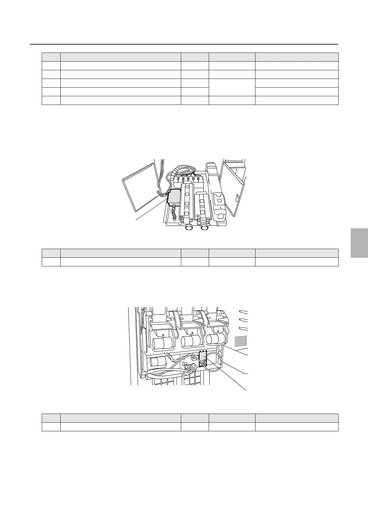
Processor section (PCB positions) (QSS-3701/3702/3703) [J]
!
!!
! Layout diagram
Tablet replenishment unit
3 Processor I/O PCB 2 ☞66211
4 Processor relay PCB ☞66220
*1
5 Processor power supply 1 PS1 ☞67400
6 Processor power supply 2 PS2
7 F replenishment I/O PCB ☞66800 only for F specification
No. Name Symbol Manual No. Remarks
1SM I/O PCB
☞66600
No. Name Symbol Manual No. Remarks
1 Tablet replenishment driver PCB
☞66500
No. Name Symbol Manual No. Remarks
1
G070039
1
G051059
Distributed by: minilablaser.com