Explanation of PCBs (Processor section)
1/3
6. Electrical parts
66210
66210
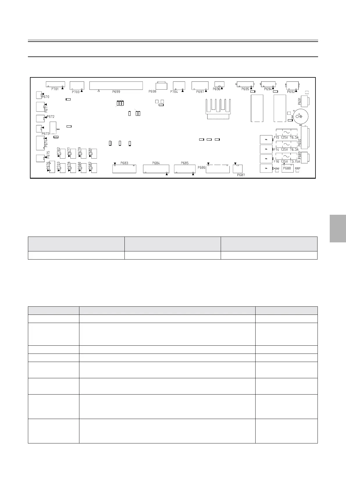
Processor I/O PCB 1 (J391468)
!
!!
! Function
• Controls each electrical part of the processor section.
!
!!
! Reference
!
!!
! Adjustments and precautions for PCB replacement
• None
!
!!
! Unused connector
Layout diagram Symptom due to the poor connection of
wiring
Symptoms of fuse blowout
☞63200 ☞4203 ☞4252
Connector No. Purpose Remarks
P671 Separated replenishment tank Option
P672 [N] [SM] [F] specifications: unused
• [J] specification: connecting to the STB tablet conveyor motor and the tablet
replenishment driver PCB
P673 Hour meter Option
P675 [N] [SM] [J] [F] specifications: unused
P676 [N] [J] [F] specifications: unused
• [SM] specification: connecting to CD circulation pump
P677 • [SM]: unused
• [N] [J] [F] specifications: connecting to CD circulation pump
P683 • [SM] [F] specifications: unused
• [N] specification: connecting to replenishment pump
• [J] specification: connecting to water supply pump
P684 [N][J] specifications: unused
• [SM]: connecting to SM I/O PCB
• [F] specification: connecting to F replenishment I/O PCB
X12
X13
IC303
LED10
LED9
LED8
LED14
LED13
LED15
LED18
LED16
LED17
LED4
LED5
LED11
LED20
LED6
LED7
TP6
TP4
LED19
TP5
TP3
LED1
LED2
LED3
TP1
TP2
G085259
Distributed by: minilablaser.com