Description of PCB (printer section)
1/1
6. Electrical parts
66090
66090
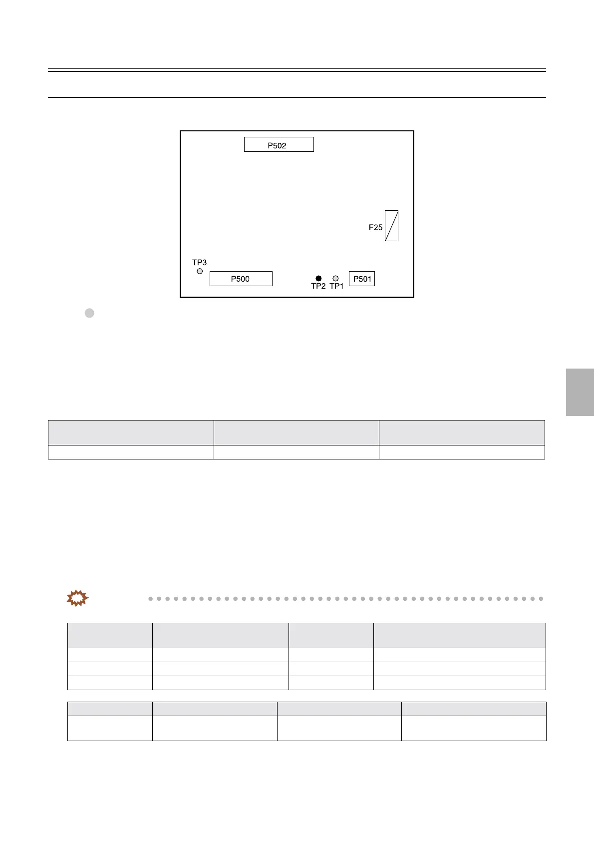
CVP PCB (J391258)
!
!!
! Function
• Controls the correction value printing unit.
!
!!
! Reference
!
!!
! Adjustments and precautions for PCB replacement
• None
!
!!
! Unused connector
• None
!
!!
! Component parts table
IMPORTANT
• Although sometimes the test pins are unmounted, the test points can be used for the measurement.
Layout diagram Symptom due to the poor connection of
wiring
Symptoms of fuse blowout
☞63000 ☞4202 ☞4252
Test point No. Purpose Measurement with
voltmeter
Remarks
TP1 DC+36 V voltage measurement Possible
TP2 Ground Possible
TP3 DC+24 V voltage measurement Possible
Fuse No. Rating Purpose Remarks
F25 T3.15 A/125 V DC+36 V power supply
protection
0 V when interlock switch is off.
Not mounted depending on conditions
G066110
Distributed by: minilablaser.com