Diagnosis appendix for the failures: Symptom due to the connection failure of wiring
1/9
4. Troubleshooting
4202
4202
Diagn osis appen dix for the fai lures: S ymptom due to t he con nection failure of wirin g
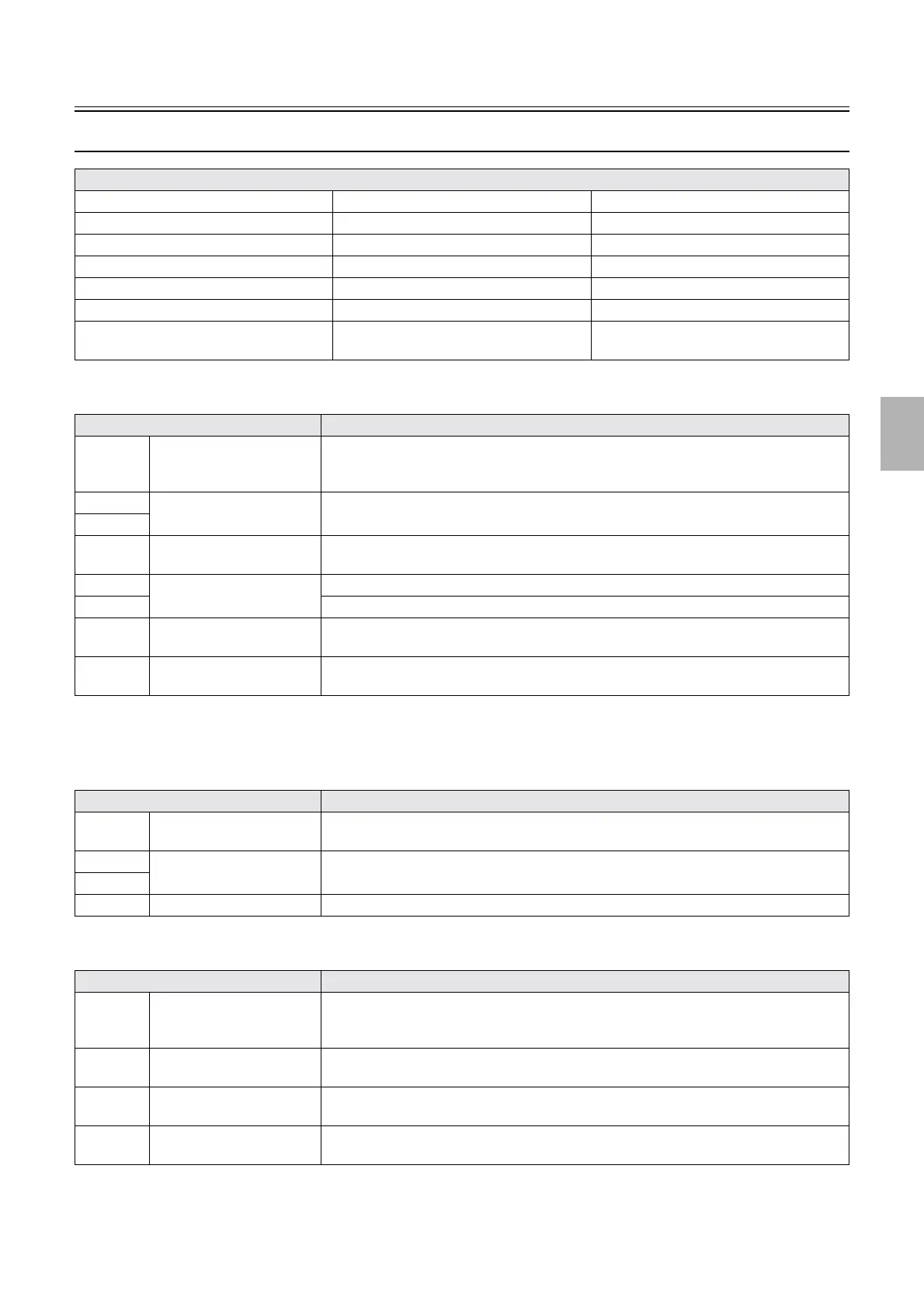
Symptom due to the connection failure of wiring (printer section)
!
!!
! Printer I/F main PCB
*1. Used only for LP7500/LP7600/LP7700/LP7900, 3702/3703/3704/3705
The suffix number of error message varies depending on the capacity booster PCB installed.
!
!!
! Capacity booster PCB
*1
!
!!
! Printer control PCB
Reference
☞Printer I/F main PCB ☞ Capacity booster PCB
*1
☞Printer control PCB
☞Laser control PCB ☞G laser driver ☞ G-AOM driver
☞Printer I/O PCB 1 ☞ Printer I/O PCB 2 ☞ Printer I/O PCB 3
☞Triple magazine PCB ☞Quad magazine PCB ☞CVP PCB
☞Printer power supply 1 (PS1) ☞Printer power supply 2 (PS2) ☞Printer power supply 3 (PS3)
☞Printer power supply 4 (PS6) ☞Printer power supply 5 (PS4) ☞Laser power supply (PS5)
☞Checking condition of wiring connection
failure
Connector No. Symptom
J/P1206 Connects to the control
power supply (+5 V)
The processor drive starts but the printer program does not start
The message Output device is not available. One moment please. . . appears when the
Maintenance Application is started
J/P1207 Connects to the laser control
PCB (ARCNET)
No.06901-00521 ARCNET communication error. Printer Processor LASER occurs.
J/P1208
J/P1211 Connects to the capacity
booster
*1
No.01920-# # # # # Capacity Booster Key was not detected. Confirm the connection
status. occurs.
J/P1213 Connects to the display
module (keyboard PCB)
Nothing is shown on the display module.
J/P1214 No key on the display module responds.
J/P455 Connects to the laser control
PCB (LVPECL)
No.06194-00008 Laser Control PCB control error. occurs.
J/P254 Connects to the ATX
motherboard (LAN)
No.01750-00000 Communication with the printer failed. The printer may not be
active, or the LAN cable may not be connected. occurs.
Connector No. Symptom
J/P860 Connects to the printer I/F
main PCB.
No.01920-# # # # # Capacity Booster Key was not detected. Confirm the connection
status. occurs.
J/P861 Connects capacity booster
PCBs F and G.
No.01920-00064 Capacity Booster Key was not detected. Confirm the connection
status. occurs.
J/P862
CN1 Unused -
Connector No. Symptom
J/P200 Connects to printer I/O PCB
1.
Printing is not started.
On the Input Check display, Interlock Switch 1 (Printer Top Cover)Interlock Switch
(Printer Door 1, 2) shows OFF.
J/P201 Connects to printer I/O PCB
2.
Printing is not started.
J/P202 Connects to printer I/O PCB
3.
No.06224-00003 Paper remains in the Processor loading unit. occurs.
J/P203 Connects to printer I/O PCB
3.
No.06224-00003 Paper remains in the Processor loading unit. occurs.
Distributed by: minilablaser.com