4/5
3. Mode
35941
35941
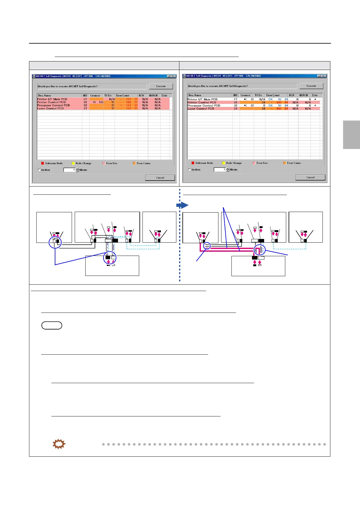
Self-diagnostic
If the number of PCB in which an error occurred is more than one (2)
The communication errors occur. Additionally prepared ARCNET cables are connected.
Diagnosis example: (Determining the failure location using the ARCNET cable)
1. Connect an additional ARCNET cable to the Printer I/F Main PCB to connect it directly to the processor control PCB, then
execute the ARCNET Self-Diagnostic program again.
If an error does not occur either in the
processor control PCB or Printer I/F Main PCB
It can be judged that both the processor control PCB and the Printer I/F Main PCB are normal.
NOTE
• An error occurs in the laser control PCB and in the printer control PCB.
• Confirm the same with the laser control PCB or the printer control PCB to narrow down the failure location.
If an error occurs in the
processor control PCB and Printer I/F Main PCB
It can be judged that the cause of failure lies in the processor control PCB or in the Printer I/F Main PCB.
1. Connect an additional ARCNET cable to the Printer I/F Main PCB to connect it directly to the printer control PCB, then
execute the ARCNET Self-Diagnostic program again.
If an error does not occur either in the printer control PCB or in the Printer I/F Main PCB
It can be judged that the cause of failure lies in the printer control PCB.
Confirm the connection status of the connector of the printer control PCB, then, if no problem is found, replace the printer
control PCB. ☞68100
If an error occurs in the printer control PCB and the Printer I/F Main PCB
It can be judged that the cause of failure lies in the Printer I/F Main PCB.
Confirm the connection status of the connector of the Printer I/F Main PCB, then, if no problem is found, replace the Printer
I/F Main PCB.
IMPORTANT
• For details about ARCNET cable cutting and cleaning of inside the ARCNET connector, see ☞68100.
J/P224
J/P223
ARCNET
ARCNET
J/P518
J/P517
J/P1517
J/P1516
J/P219
J/P220
J/P222
J/P221
Processor
control PCB
Printer control PCB
Laser control
PCB
Printer I/F main PCB
J/P224
J/P223
ARCNET
J/P518
J/P517
J/P1517
J/P1516
J/P219
J/P220
J/P222
J/P221
Processor
control PCB
Printer control PCB
Laser control
PCB
Printer I/F main PCB
J/P1208
J/P1207
J/P1208
J/P1207
Connection of normal ARCNET cables
Connection of additionally prepared ARCNET cables
Disconnect the cables.
Disconnect the
cable.
Disconnect the
cable.
Connect additionally prepared cables.
Distributed by: minilablaser.com