3/3
3. Mode
35951
35951
Self-diagnostic
Synchronous Detection Setting Value G turns normal
• Failure in the G-AOM driver
NOTE
• When Synchronous Detection Setting Value R or B is abnormal and confirming no connection failure in wiring
between the laser control PCB and the laser unit does not improve the symptom, there is a possibility of failure in the
laser unit or in the laser control PCB.
7. Synchronization frequency is abnormal
• Confirm that there is no connection failure in wiring between the laser control PCB and the laser unit.
• Confirm that there is no connection failure in wiring between the laser control PCB and the G-AOM driver.
• Failure in the G-AOM driver
• Failure in the laser control PCB
• Failure in the laser unit
8. Result of Polygon mirror (Locked) is abnormal
• Confirm that power (24 V) is supplied to the laser control PCB.
• Confirm that there is no connection failure in wiring between the laser control PCB (J/P1515) and the laser unit.
• Failure in the laser control PCB
• Failure in the laser unit
!
!!
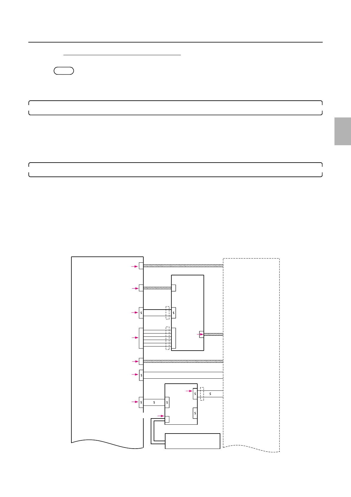
! Connection failure in wiring
Displayed are major errors that occur between the laser control PCB and the laser unit when connection failure in each PCB connector
occurs.
Utilize this in addition to the above diagnosis for better diagnosing.
(1T)
1
(MiniCT-18P)
NOT USED
10
7
6
4
3
2
1
J/P1515
J/P1508
J/P1543
(VH-7P)
J/P1502
J/P1501
J/P1663
10
1
10
P1666
J/P1664
J/P1637
J/P1638
J/P1639
J/P1636
1
LASER UNIT
J/P1519
1
12
2
1
12
1
G LASER DRIVER
G-AOM DRIVER
J/P1503
(BNC)
10
6
7
6
4
3
2
1
5
1
(BNC)
(BNC)
(BNC)
No.6073
No.6073
No.6073
No.6073
No.6073
No.6075
No.6073
No.6073
No.6073
LASER CONTROL PCB
J/P1665
No.6106
Power supply PCB (+5 V)
G085179
Distributed by: minilablaser.com