4/9
3. Mode
36080
36080
Printer Mechanical Adjustment
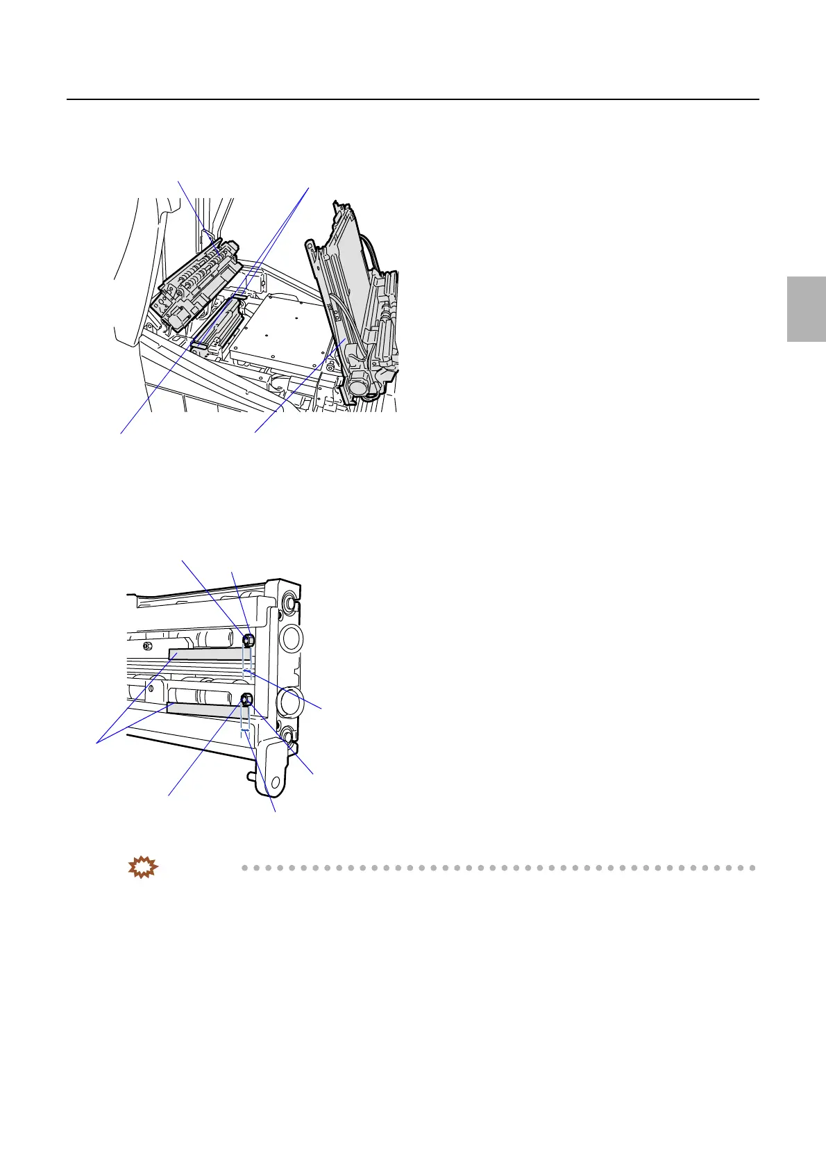
3. Lift up paper advance units 1 and 2.
4. Remove the pressure guide. (two locks)
5. Check that the dimension of inlet roller adjusting screw of exposure advance unit is between 2.0 and 2.5
mm. If an adjustment is necessary, loosen the nut of the inlet roller and adjust the screw. (Loosen one
nut, adjust one screw.)
IMPORTANT
• Make a test print again. Measure the lengths between 0 mm-line and 254 mm-line on right and left edges of the
test print. If the difference is not within 0.2 mm, carry out the following adjustment.
• Adjust the zigzagging by turning the adjusting screw between 2.0 and 2.5 mm. If adjustment is performed out of
the range between 2.0 and 2.5 mm, the banding appears on the area 32 mm from the paper front end.
6. Loosen the fixing screw of the exposure advance unit inlet roller. (Loosen one fixing screw.)
7. Loosen the nut of the exposure advance unit inlet roller. (Loosen one nut.)
Paper advance unit 2
Pressure guide
Paper advance unit 1
Locks
G068468
Inlet roller adjusting screw
Exit roller nut
Exit roller adjusting screw
Scales
2.0 to 2.5 mm
Inlet roller nut
2.0 to 2.5 mm
G072395
Distributed by: minilablaser.com