2. Replacement and adjustment of parts
25620
2/3
25620
Paper supply unit
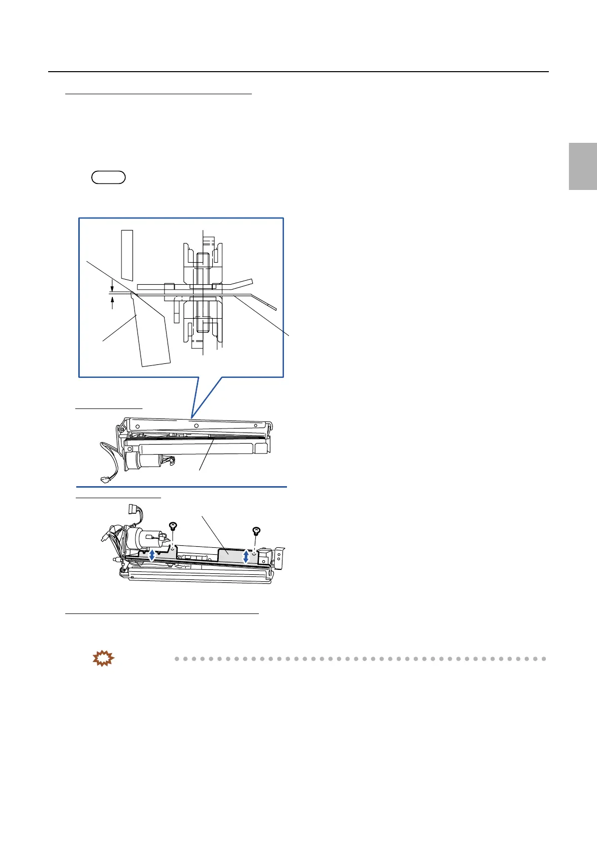
Adjusting the position of the sensor holder
1. Reattach the cutter cover. (two screws)
2. Attach the mounting angle bracket. (one screw)
3. Fix the sensor holder temporarily. (two screws)
4. Position the sensor holder so that it is 0 to 0.5 mm lower than the cutter lower blade. (two screws)
NOTE
• Usually, if the cutter lower blade is contacted and the sensor holder is attached, it becomes within the above standard
range. Finally, confirm the standard dimension of the sensor holder and cutter lower blade.
The right angle adjustment of the cutter unit
1. Loosen two screws on the cutter unit positioning plate, then carry out the right angle adjustment using
the adjustment screw. (Loosen one screw and one nut.)
IMPORTANT
• Loosen two screws on the cutter unit and test the right angle adjustment for the cutter unit.
0 to 0.5
mm
Sensor holder
Cutter lower
blade
Sensor holder
Cutter lower blade
Cutter unit back face
Cutter unit front front face
Contact
G068532
Distributed by: minilablaser.com