Replenishment operation sequence [F]
1/8
5. Operation sequence
57010
57010
Replen ishment opera tion se quence [F]
Replenishment operation sequence [F]
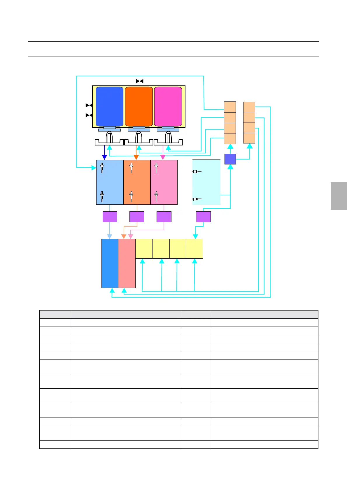
Piping diagram
• This section explains the replenishment operation flow.
Symbol Name Symbol Name
SE60 Cartridge sensor MV4 P1R cartridge flushing valve
SE61 Cartridge position sensor (upper) MV5 P2RA cartridge flushing valve
SE62 Cartridge position sensor (lower) MV6 P2RB cartridge flushing valve
SE63 P1R (upper) replenishment solution level sensor MV7 P1R agitation solenoid valve
SE64 P1R (lower) replenishment solution level sensor MV8 P1 automated cleaning valve
SE65 P2RA (Upper) Replenishment Solution Level
Sensor
MV9 P2 automated cleaning valve
SE66 P2RA (Lower) Replenishment Solution Level
Sensor
MV10 PS automated cleaning valve
SE67 P2RB (Upper) Replenishment Solution Level
Sensor
P17 Replenisher cartridge cleaning pump
SE68 P2RB (Lower) Replenishment Solution Level
Sensor
RP1 P1R Replenisher Pump
LSE7 PSR (Upper) Replenishment Solution Level Sensor RP2 P2RA Replenisher Pump
LSE8 PSR (Lower) Replenishment Solution Level
Sensor
RP3 P2RB Replenisher Pump
- - RP4 PSR Replenisher Pump
P17
MV8
MV9
MV10
MV7
MV4
MV5
MV6
P2RAP1R
PSR
R
P
2R
P
3R
P
4
P1 P2 PS-3PS-2PS-1 PS-4
P2RA
P1R
P2RB
P2RB
R
P
1
SE63
SE64
SE65
SE66
SE67
SE68
LSE7
LSE8
SE60
SE61
SE62
Replenisher tank
Replenishment
cartridge
Processing tank
G085080
Distributed by: minilablaser.com