6. Electrical parts
63280
3/4
63280
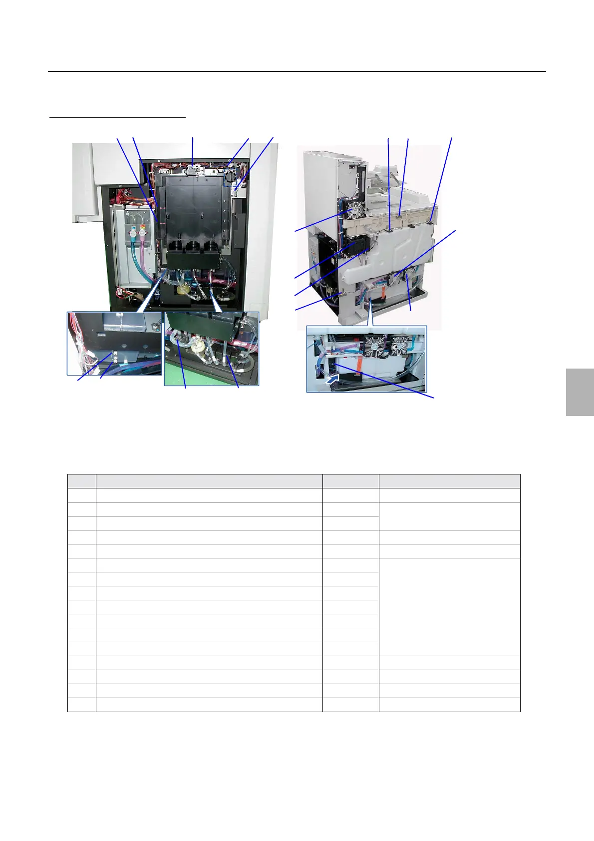
Positions of electrical parts (Processor section)
!
!!
! Layout diagram
Processor section (back face)
No. Name Symbol Remarks
1 Replenisher Cartridge Set Sensor SE60
2 Replenisher Cartridge Position Sensor (Upper) SE61
*3
3 Replenisher Cartridge Position Sensor (Lower) SE62
4 Replenishment cartridge opening motor DM5
*3
5 Interlock Switch (Replenisher Section Door) LS8
6 P1R cartridge flushing valve MV4
*3
7 P2RA cartridge flushing valve MV5
8 P2RB cartridge flushing valve MV6
9 P1R agitation solenoid valve MV7
10 P1 automated cleaning valve MV8
11 P2 automated cleaning valve MV9
12 PS automated cleaning valve MV10
13 Automated cleaning valve - Unused
14 Replenisher cartridge cleaning pump P17
*3
15 PSR (Upper) Replenishment Solution Level Sensor LSE7
16 PSR (Lower) Replenishment Solution Level Sensor LSE8
5
20
4
15
1
14
2
3
• R e a r
13, 12, 11, 10
• Front
6, 7, 8, 9
16
21
23
22
24
25
27 28
26
• R e a r : 1 7
• Middle: 18
• F r o n t : 1 9
QSS-3701/3702/3703/LP7500/LP7600 [F]
G085330
Distributed by: minilablaser.com