2/2
6. Electrical parts
66020
66020
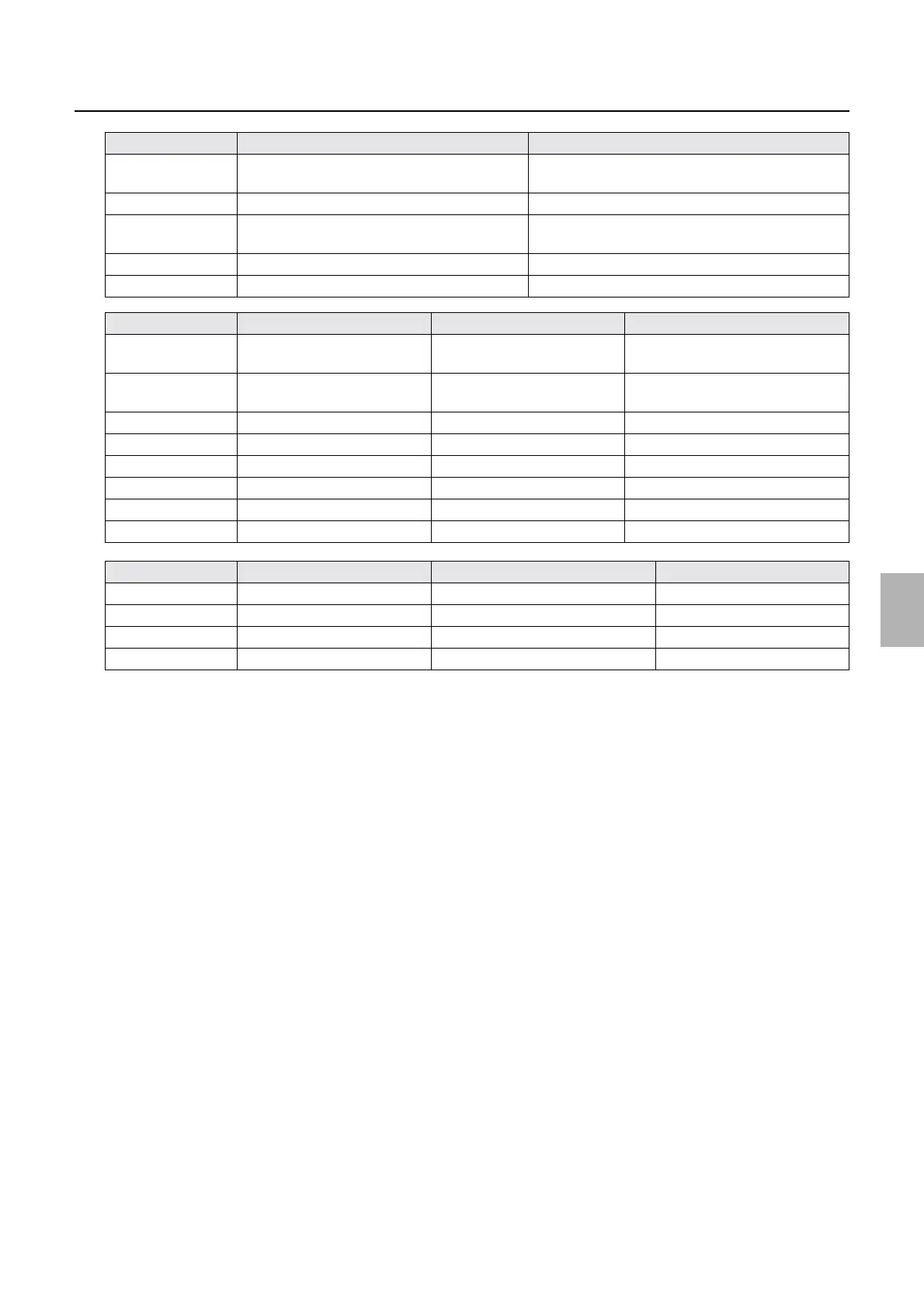
Description of PCB (printer section)
LED2 DC+24 V-2 input check ON when power is supplied, OFF when the interlock
switch is off.
LED3 DC+24 V input check On when the power supply is turned on.
LED4 DC+36 V input check ON when power is supplied, OFF when the interlock
switch is off.
LED5 DC+5 V input check On when the power supply is turned on.
LED6 For checking the interlock OFF when the interlock switch is off.
Test point No. Purpose Measurement with voltmeter Remarks
TP1 DC+24 V−1 voltage
measurement
Possible 0 V when interlock switch is off.
TP2 DC+24 V−2 voltage
measurement
Possible 0 V when interlock switch is off.
TP3 DC+24 V voltage measurement Possible
TP4 DC+36 V voltage measurement Possible 0 V when interlock switch is off.
TP5 DC+5 V voltage measurement Possible
TP6 DC+5 V interlock check Possible 0 V when interlock switch is off.
TP7 Ground Possible
TP8 Ground Possible
Fuse No. Rating Purpose Remarks
F32 T6.3 A/125 V DC+24 V−1 power supply protection
F33 T6.3 A/125 V DC+24 V−2 power supply protection
F34 T3.15 A/125 V DC+24 V power supply protection
F35 T6.3 A/125 V DC+36 V power supply protection
LED No. Purpose Status
Distributed by: minilablaser.com