2/2
6. Electrical parts
66600
66600
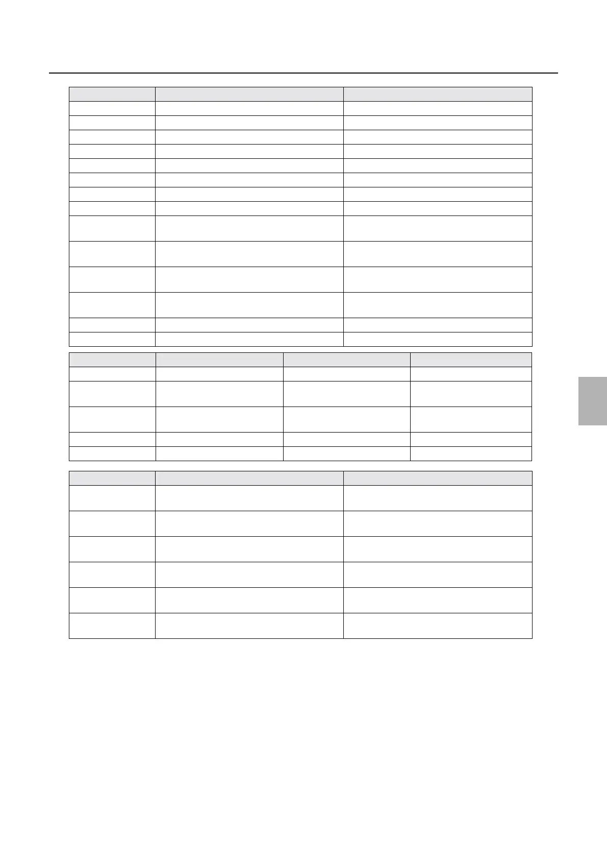
Explanation of PCBs (Processor section)
LED2 CD−B replenishment solution presence check ON when there is replenishment solution.
LED3 CD−C replenishment solution presence check ON when there is replenishment solution.
LED4 STB replenishment solution presence check ON when there is replenishment solution.
LED5 BF−A replenishment solution presence check ON when there is replenishment solution.
LED6 BF−B replenishment solution presence check ON when there is replenishment solution.
LED7 DC+5 V input check On when the power supply is turned on.
LED8 DC+24 V−A input check On when the power supply is turned on.
LED9 DC+24 V−B input check On when the power supply is turned on.
LED10 SSR12 operation check (CD−A replenisher
pump)
ON during operation
LED11 SSR13 operation check (CD−B replenisher
pump)
ON during operation
LED12 SSR14 operation check (CD−C replenisher
pump)
ON during operation
LED13 SSR15 operation check (BF−A replenisher
pump)
ON during operation
LED14 SSR16 operation check (BF−B replenisher pump) ON during operation
LED15 SSR17 operation check (STB replenisher pump) ON during operation
Test point No. Purpose Measurement with voltmeter Remarks
TP1 DC+5 V voltage measurement Possible
TP2 DC+24 V−A voltage
measurement
Possible
TP3 DC+24 V−B voltage
measurement
Possible
TPG1 Ground Possible
TPG2 Ground Possible
VR No. Purpose Remarks
VR1 CD−A replenishment solution sensor sensitivity
adjustment
VR2 CD−B replenishment solution sensor sensitivity
adjustment
VR3 CD−C replenishment solution sensor sensitivity
adjustment
VR4 STB replenishment solution sensor sensitivity
adjustment
VR5 BF−A replenishment solution sensor sensitivity
adjustment
VR6 BF−B replenishment solution sensor sensitivity
adjustment
LED No. Purpose Status
Distributed by: minilablaser.com