RX2530 M4 Upgrade and Maintenance Manual 229
Expansion cards and backup units
Example two Retimer controllers in riser modules 2 and 3
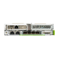
Figure 146: Connecting cables - first Retimer controller
Ê Connect the VPP cable (1) to the Retimer controller.
Ê Connect the color-coded Oculink cable (2) to the Retimer controller.
Ê Install the first Retimer controller in riser module 2.
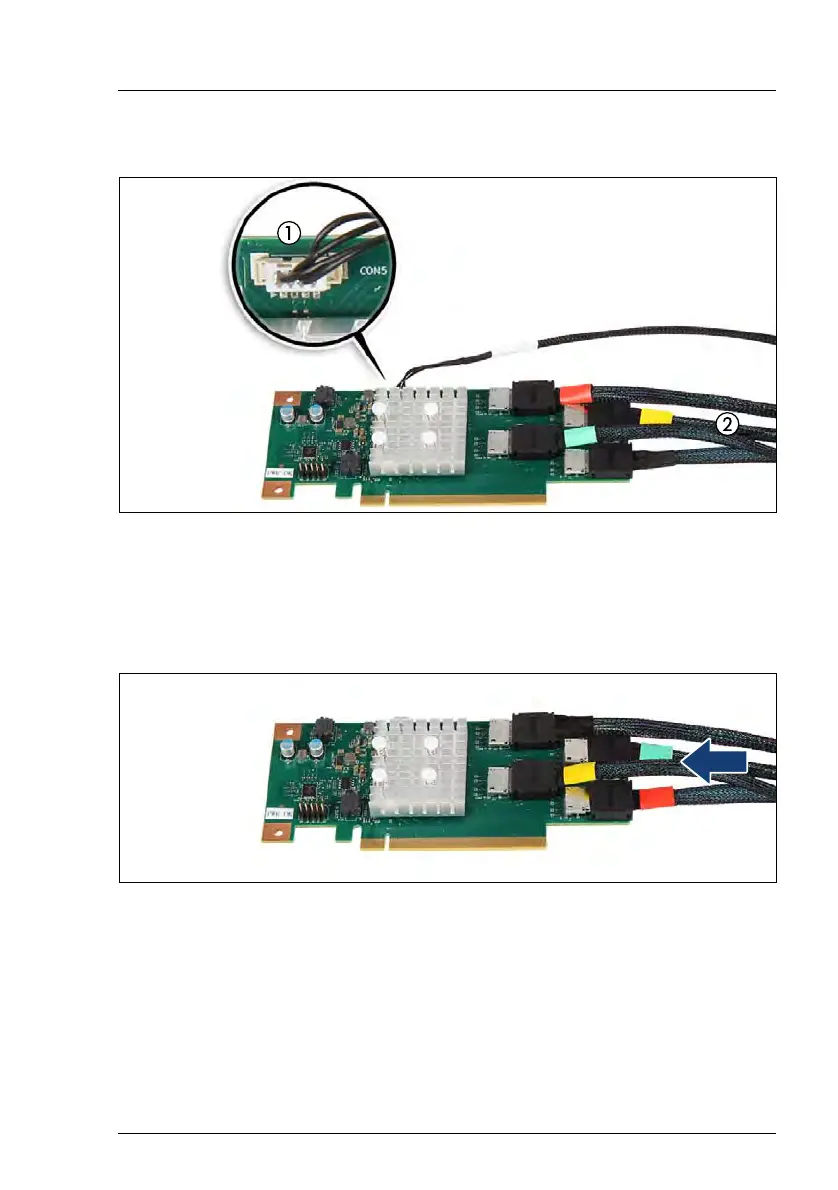
Figure 147: Connecting cables - second Retimer controller
Ê Connect the color-coded Oculink cable to the Retimer controller.
V CAUTION!
The Oculink cable is connected in mirrored order as for the first
Retimer controller!
Ê Install the second Retimer controller in riser module 3.

 Loading...