230 Upgrade and Maintenance Manual RX2530 M4
Expansion cards and backup units
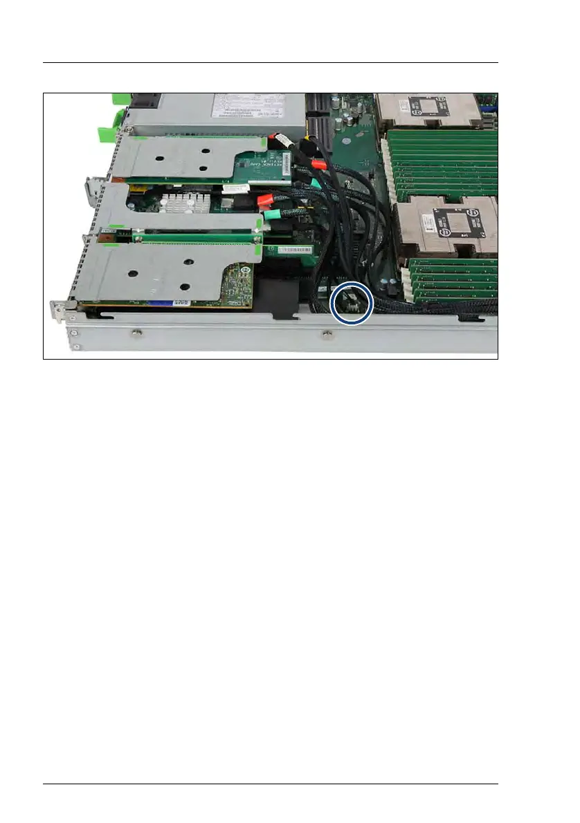
Figure 148: Example - Retimer controllers in riser module 2 and 3
Ê Connect the VPP cable from the first Retimer controller in riser module 2 to
connector "VPP CPU1" on the system board.
Ê Connect the color-coded Oculink cables to the corresponding HDD
backplane (see section "Replacing a 10x 2.5-inch HDD backplane" on
page 175).
9.5.1.4 Concluding steps
Ê Install the corresponding riser module, see section "Installing a riser module"
on page 68.
Ê "Reassembling" on page 57
Ê "Connecting the power cord" on page 63
Ê "Switching on the server" on page 66
Ê If applicable, update the system information of your server using the Chassis
ID Prom Tool, see section "Using the Chassis ID Prom Tool" on page 103.
Select the corresponding system name (for example "at EP5x0i").
Ê "Updating expansion card firmware" on page 85
Ê "Enabling Option ROM scan" on page 86
Ê "Resuming BitLocker functionality" on page 98

 Loading...