RX2530 M4 Upgrade and Maintenance Manual 427
17.2.3 Server rear
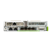
17.2.3.1 Connectors on the I/O panel
Figure 319: Connectors on the I/O panel
I Depending on the BIOS settings, the shared LAN connector may also be
used as a management LAN connector. For more information, see the
corresponding BIOS Setup Utility reference manual.
Note for LAN connectors on OCP modules
The LAN connectors on the OCP modules are numbered in ascending order
from right to left beginning with “0”.
Pos. Description
1 USB 3.0 connector
2 OCP module (optional, different variants)
3 USB 3.0 connector
4 Management LAN connector (for iRMC S5 server management
function)
5 Shared LAN connector (LAN1)
6 LAN connector (LAN2)
7 Video connector (VGA)

 Loading...