GE
P
ART NUMBER FN091065, REVISION 2 VS5 N AND VS6 N SERVICE MANUAL
Chapter 5 - Components and Function (Theory) 5-3
PRELIMINARY
5-2-2 Signal Flow
The two TR32 Boards in the Front-End Processor generate the strong bursts transmitted by the probes
as ultrasound into the body. The Transmit bursts are routed from the TR32 Boards via the Probe
Interface Board (PIB), then to the Probe Selection Board (PSB) via PIB-to-PSB flex where the
ultrasound probes are connected.
Weak ultrasound echoes from blood cells and body structure are received by the probes and routed via
the Probe Selection Board, the PIB-to-PSB flex and the Probe Interface Boards back to the
TR32 Boards. The TR32 Boards amplify these signals, convert them to a digital signal and do the beam
forming.
The vector data streams (one per each MLA) generated by the Beam Former are routed to the
RFI Board for further processing by the Demodulator FPGA and DSP and then the signals are
transferred via the PCI bus to the Back-End Processor where they are converted to video. The video
signals are connected to the Distribution Interface Board (DIB) from where they are routed to the internal
monitor, to the external monitor, and to the Digital Video Recorder (DVR).
5-2-2-1 System Configuration and Software
System configuration is stored on a hard disk drive inside the Back-End Processor.
At power up, all necessary software is loaded from the hard disk.
5-2-2-2 Operator Panel
The user initiates system operations via the Operator Panel that has ultrasound-specific buttons,
mode-dependent softkey buttons and an alphanumeric keyboard.
5-2-2-3 Electronics
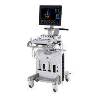
Vivid™ S5 N and Vivid™ S6 N internal electronics are divided into three:
• Front End (FE) Processor
• Back End Processor (BEP)
• Power Distribution System
For both Vivid™ S5 N and Vivid™ S6 N systems, internal electronics comprise a single card cage that
contains both the FEP and the BEP. The Interconnecting signals and power distribution between the
two sections are routed internally via cables. All the interconnections to the monitors, operator keyboard
and peripherals are via the Distribution Interface Board (DIB) which is fully shielded for EMC/EMI
purposes.
The main functional blocks in the Vivid™ S5 N and Vivid™ S6 N systems are listed below, and
described in detail in this chapter, as follows:
• Front End (FE) Processor - see Section 5-3 "Front End Unit" on page 5-5
• Back End Processor (BEP) - see Section 5-4 "Back End Processor" on page 5-22
• Internal and external cable interconnections - see Section 5-5 "Internal and External Input/Output
(I/O)" on page 5-31
• Monitor & Keyboard - see Section 5-7 "Top Console with Monitor and Operator Panel" on page 5-45
• Power Supply System - see Section 5-6 "Power Supply System" on page 5-38
• Peripherals - see Section 5-9 "Peripherals" on page 5-52
For a detailed block diagram of the Vivid™ S5 N and Vivid™ S6 N system, refer to Figure 5-2 "System
Block Diagram" on page 5-4.

 Loading...