GE
P
ART NUMBER FN091065, REVISION 2 VS5 N AND VS6 N SERVICE MANUAL
Chapter 8 - Replacement Procedures 8-65
PRELIMINARY
8-4-3 Joint Assembly Replacement Procedure
8-4-3-1 Tools
Use the appropriate flat and Phillips type screwdrivers and the appropriate Allen keys.
8-4-3-2 Preparation
Shut down the Vivid S5 N or Vivid S6 N ultrasound unit, as described in 4-2-3 "Power Shut Down" on
page 4-7.
8-4-3-3 Joint Assembly Removal Procedure
1) Remove the Monitor as described in the “Monitor Removal Procedure” on page 8-26.
2.) Remove the Keyboard Assembly as described in the “Keyboard Assembly Removal Procedure” on
page 8-39
3) Remove the Probe shelf as described in the “Probe Shelf Removal Procedure” on page 8-52.
4.) Remove the Lower Arm as described in the “Lower Arm Removal Procedure” on page 8-193.
5.) Remove the Keyboard Interface Assembly as described in the “Keyboard Interface Assembly
Removal Procedure” on page 8-44.
6.) If the rear tray is attached to the system, remove it.
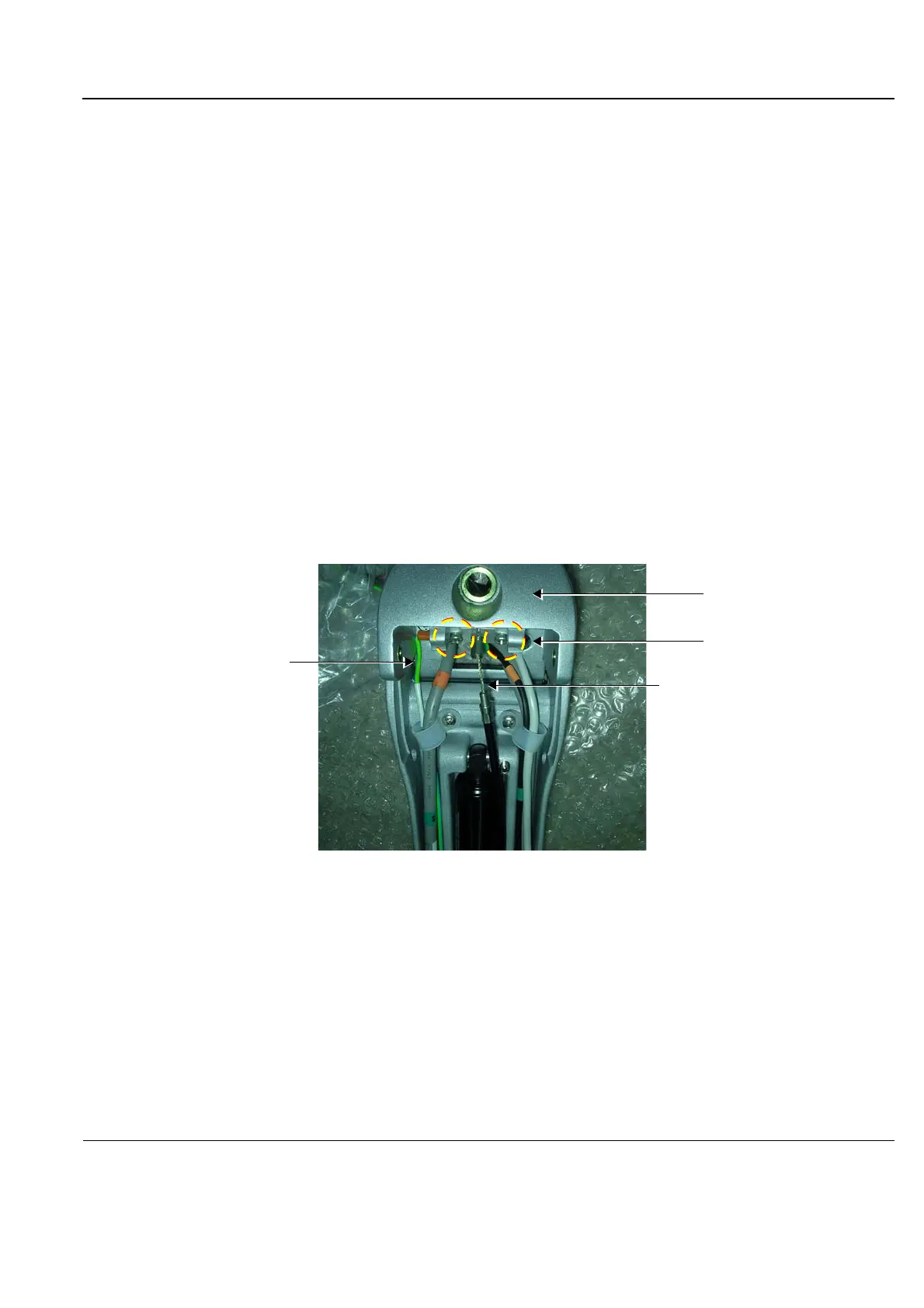
7.) Dismantle the Upper Gas Spring Cable Assembly by removing the two securing screws and bracket
- Figure 8-80.
8.) Disconnect the Ground lead.
Figure 8-80 Dismantling the Upper Gas Spring Cable Assembly
Gas Spring Cable
Retaining Screws
securing Upper Gas Spring
Cable Assembly
Joint Assembly
Ground Lead

 Loading...


