GE
P
ART NUMBER FN091065, REVISION 2 VS5 N AND VS6 N SERVICE MANUAL
Chapter 8 - Replacement Procedures 8-87
PRELIMINARY
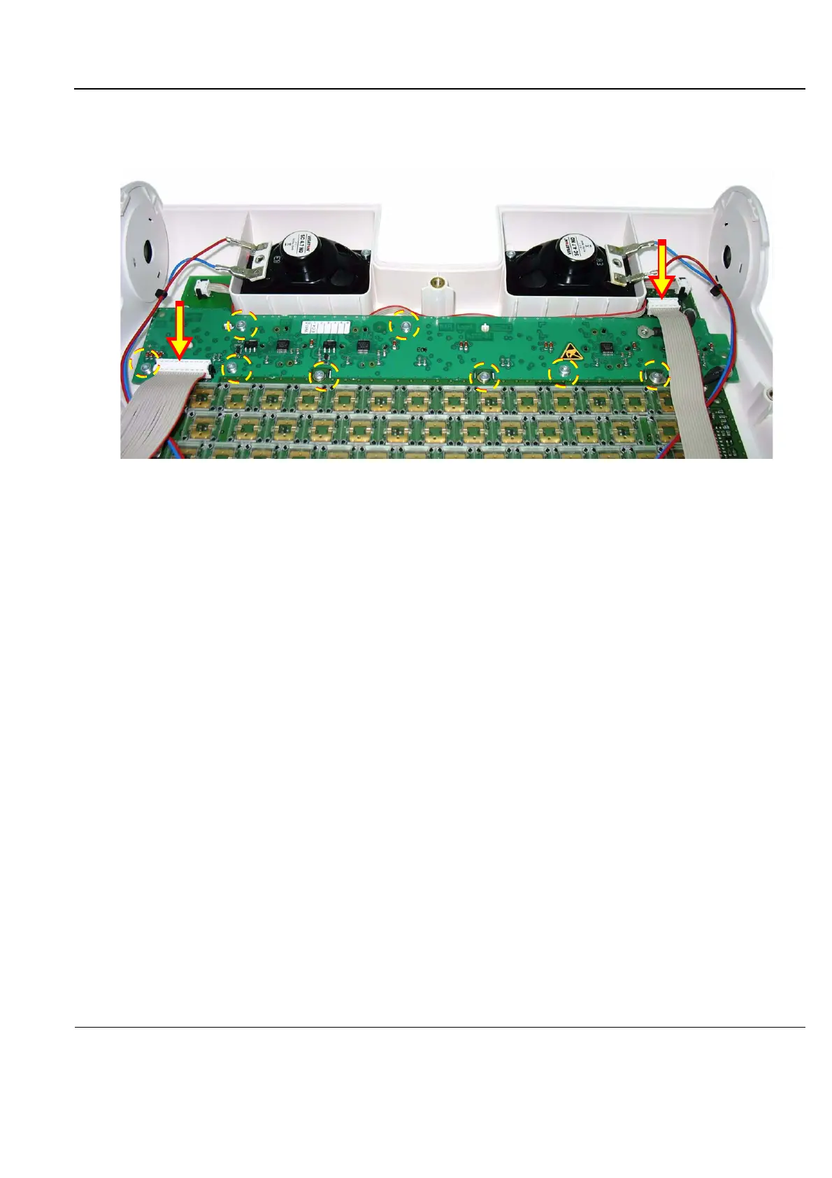
4.) Unscrew the 10 Torx retaining screws and remove them from the LED and Soft Menu Board - those
visible in Figure 8-101 are encircled.
5.) Disconnect the two flat cables (indicated with arrows in Figure 8-101).
6.) Lift up and remove the LED and Soft Menu Board.
8-4-10-4 LEDs and Soft Menu Board Installation Procedure (New-type Operator Panel)
1.) Carefully place the replacement LED and Soft Menu Board into the operating panel, positioning it
correctly on the plastic retaining holders. Press the Board gently into its home position.
2.) Return and fasten the 10 Torx screws (previously removed) to secure the board firmly in place.
3.) Reconnect the two flat cables (previously disconnected).
4.) Refit the Keyboard Bottom Cover, and secure it with the screws previously removed - as described
in the “Keyboard Bottom Cover Removal Procedure” on page 8-59.
5.) Re-fit the Keyboard Assembly, as described in the “Keyboard Assembly Removal Procedure” on
page 8-39.
6.) Proceed to perform the following functionality tests:
- “Alphanumeric Keyboard Test” on page 4-18
- “Extended Keyboard and Trackball Test” on page 4-18
- “Speakers Tests” on page 4-21
- “Light Detector Test for Vivid S6 N only” on page 4-22
- “USB Test” on page 4-37
- “Grounding Continuity” on page 10-23
- “Chassis Current Leakage Test” on page 10-24
Figure 8-101 LED and Soft Menu Board

 Loading...


