GE
P
ART NUMBER FN091065, REVISION 2 VS5 N AND VS6 N SERVICE MANUAL
8-74 Section 8-3 - Control Console Components Replacement Procedures
PRELIMINARY
8-4-6 TGC Board Replacement Procedure (New-type Operator Panel)
NOTE: The procedures described in this section are applicable to all Vivid S5 N / Vivid S6 N systems supplied
with the new-type Operator Panel (Figure 8-93).
NOTE: For Vivid S5 N / Vivid S6 N systems with the older-type Operator Panel, refer to the instructions
provided in “TGC Board Replacement Procedure (Old-type Operator Panel)” on page 8-77.
8-4-6-1 Tools
Use the appropriate flat screwdriver and T10 Torx screwdriver (T8 may also be used), as indicated in
the TGC Board replacement procedure.
8-4-6-2 Preparation
Shut down the Vivid S5 N or Vivid S6 N ultrasound unit, as described in 4-2-3 "Power Shut Down" on
page 4-7.
8-4-6-3 TGC Board Removal Procedure (New-type Operator Panel)
1.) Remove the Keyboard Assembly, as described in the “Keyboard Assembly Removal Procedure” on
page 8-39.
2.) Place the Keyboard Assembly face-up on a flat, clean, stable surface.
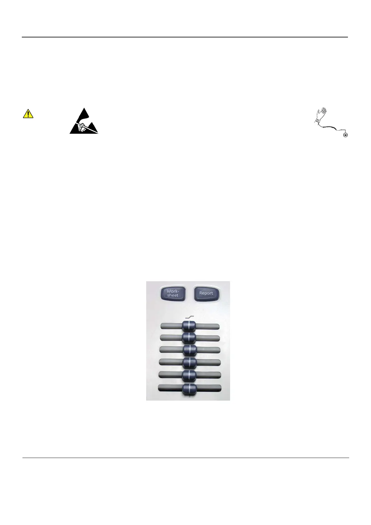
3.) Remove the 6 silicone slider buttons by gently pulling each one upwards to release each button.
4.) Carefully turn the Keyboard Assembly upside-down.
5.) Loosen and remove the four retaining screws - encircled in Figure 8-91.
When performing these procedures, take precautions to avoid damage of
electrostatic-sensitive components. Always have the ESD wrist strap
connected either to the DIB chassis or to the GND plug at the rear of the
scanner, and to your hand.
If a battery is present, first remove the battery as it contains stored energy.
Refer to “Battery Removal Procedure” on page 8-116.
Figure 8-90 TGC Slider Panel

 Loading...


