GE
P
ART NUMBER FN091065, REVISION 2 VS5 N AND VS6 N SERVICE MANUAL
Chapter 8 - Replacement Procedures 8-187
PRELIMINARY
8-6-17-4 AC Distribution Box (Type A) Installation Procedure
1.) Inspect the rubber bumpers on the AC Box housing (see Figure 8-235) and if necessary, replace.
2.) Connect the new fan’s electrical cable to the cable connector that protrudes from the new AC Box.
(Refer to Figure 8-235).
3.) Position the new Fan Assembly on the four retaining pins on the new AC Box (refer to Figure 8-235).
4.) Return and fasten the four retaining screws (previously removed) to secure the Fan Assembly onto
the AC Box Assembly.
NOTE: The AC Box Assembly is supplied with two jumpers to alter the input power supply
(220 - 240 V and 110 -120 V, as applicable).
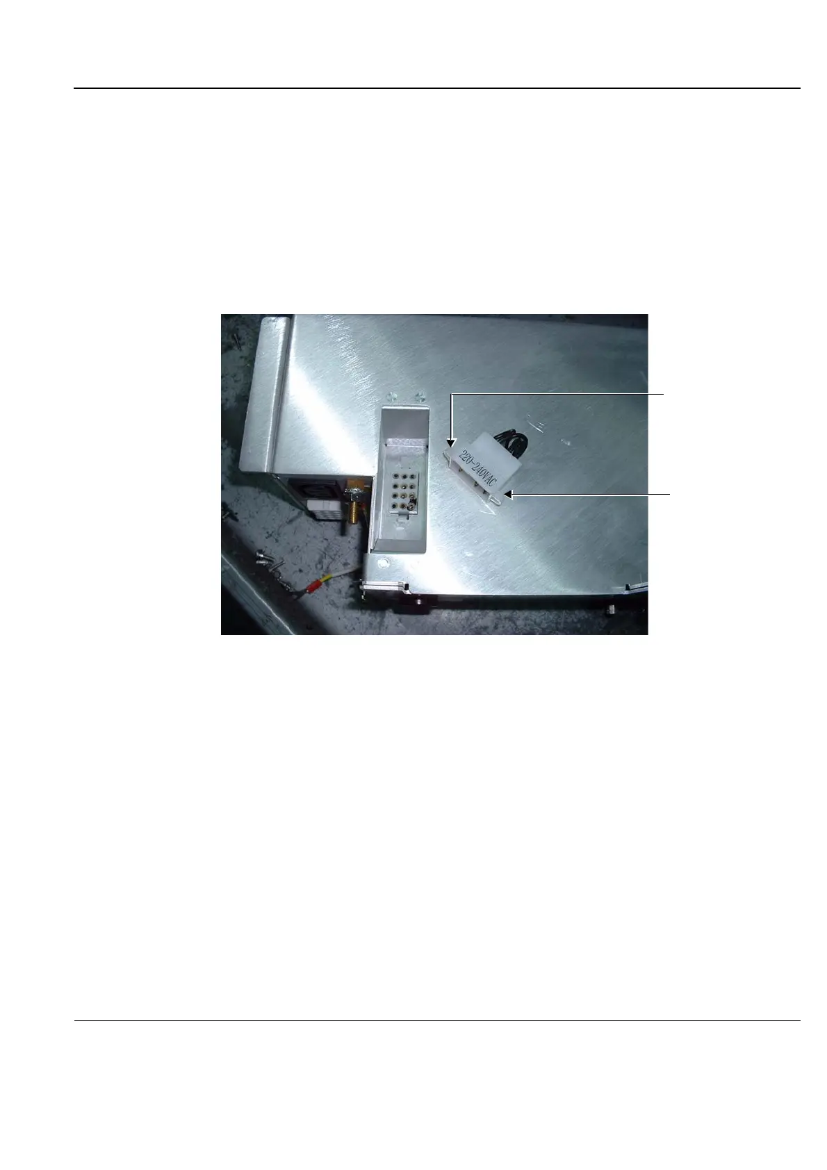
5.) To remove the jumper, squeeze the two plastic retaining clips (Figure 8-236) together and pull the
jumper away from its base.
Return the appropriate jumper to its socket according to the required voltage.
Note: For 220 V systems, the jumper can only be inserted in one position.
6.) Place the AC Box in position at the rear of the system by sliding it onto the support rails and pushing
it all the way to the end.
7.) Return the two supporting screws (previously removed) to their positions and fasten them securely
(refer to Figure 8-233).
8.) Reconnect the power cables.
9.) Reconnect the earth leads - refer to note below.
Figure 8-236 AC Box Showing Jumper with Two Retaining Clips
Retaining Clip
Retaining Clip

 Loading...


