GE
P
ART NUMBER FN091065, REVISION 2 VS5 N AND VS6 N SERVICE MANUAL
8-106 Section 8-3 - Control Console Components Replacement Procedures
PRELIMINARY
8-5-1-4-1 Installing the Cables in the Monitor Arm Assembly
The cables are threaded from the Keyboard Interface Assembly to the Monitor Arm Assembly and
upwards to the LCD monitor; in the process, the previously-dismantled parts are re-installed.
Proceed as follows:
1.) Re-fit the lower arm, as described in the “Lower Arm Installation Procedure” on page 8-196.
2.) Return the up/down lever to its central position and secure it using the screw and nut (previously
removed).
Use an Allen key to secure the lever firmly in position - refer to Figure 8-116 on page 8-99.
3.) Secure the cables with two tie wraps, as indicated in Figure 8-115 on page 8-99.
4.) Thread the thinner, black power cable through the aperture in the Monitor Arm assembly and push
it upwards - Figure 8-127.
5.) Thread the thicker, grey DVI cable - together with the attached ferrite - through the opening in the
Monitor Arm assembly and push it upwards - Figure 8-127.
6.) Return and wind the plastic spiral cable protector around the cables, as shown in Figure 8-114.
Start the spiral of the plastic cable protector at the level of the Monitor Arm retaining bolt.
7.) Return the alignment block (previously removed) and using an Allen key, fasten it securely as
shown in Figure 8-113. (Take care not to damage the cables).
Note: A detailed description of the procedure for returning the Alignment Block is described in the
“Monitor Arm Installation Procedure” on page 8-33.
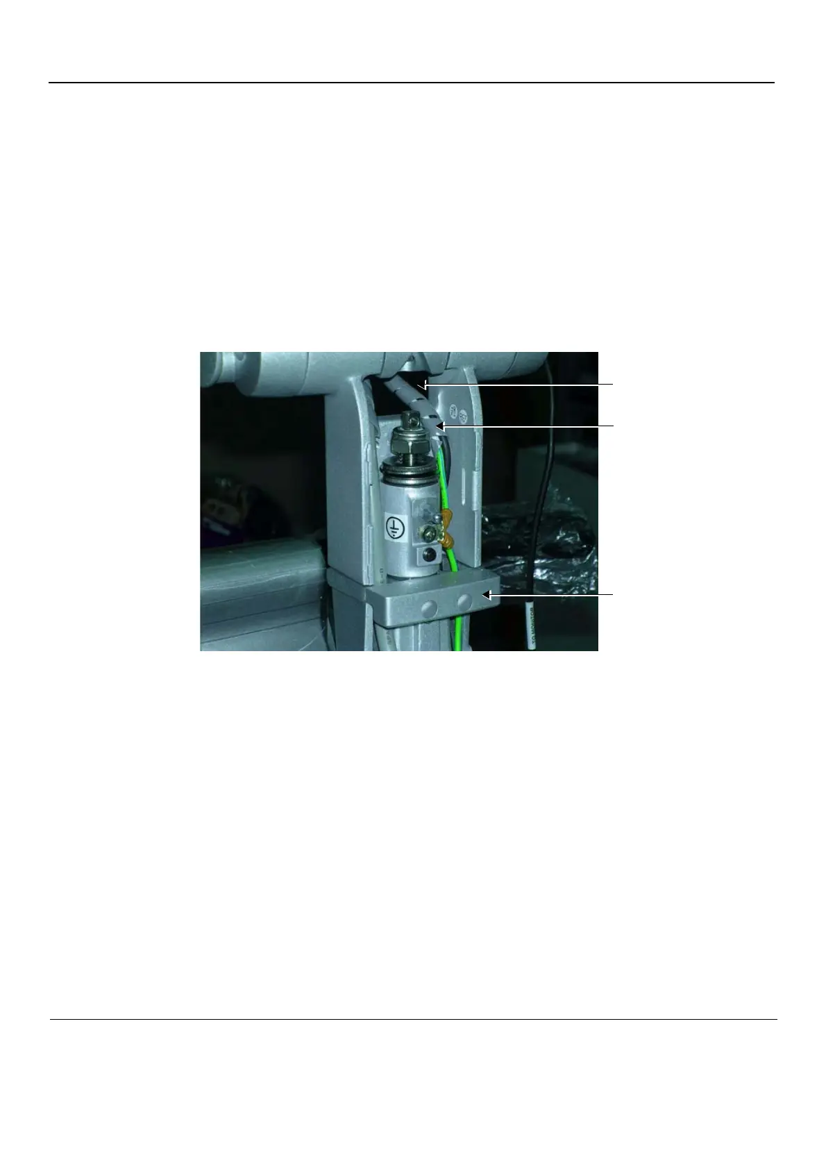
Figure 8-127 Cable Aperture in the Monitor Arm Assembly
Thread cables through the
aperture in the Monitor Arm
Assembly
Plastic spiral protector starts
at the level of the retaining bolt
Bracket (shown with
protective screw caps)

 Loading...


