GE
P
ART NUMBER FN091065, REVISION 2 VS5 N AND VS6 N SERVICE MANUAL
8-98 Section 8-3 - Control Console Components Replacement Procedures
PRELIMINARY
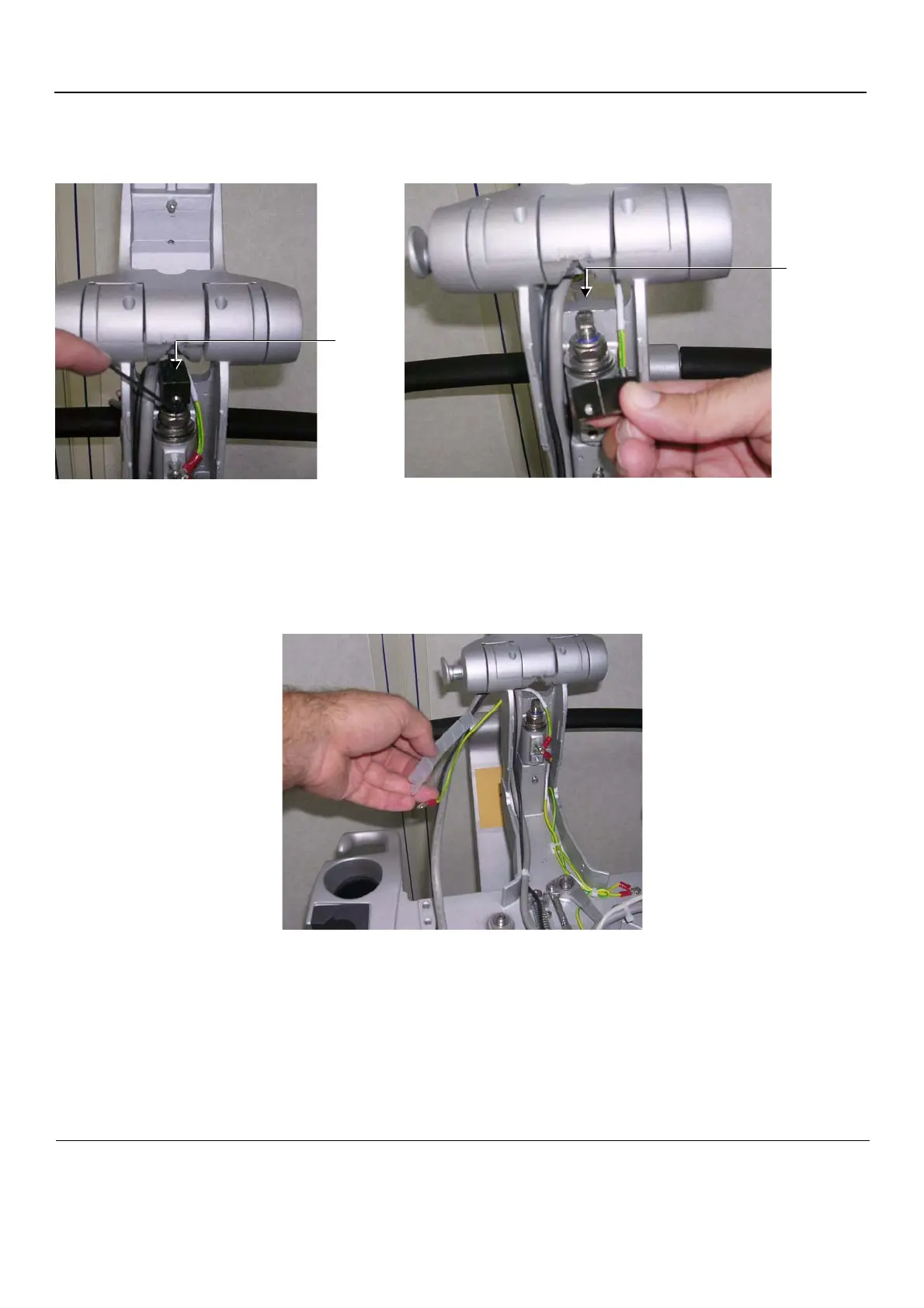
3.) Using an Allen key, remove the Alignment Block as shown in Figure 8-113.
If necessary, use a flat screwdriver for leverage when loosening the block, taking care not to
damage the cables.
4.) Slide the DVI cable (the thicker, grey cable) - together with the attached ferrite - through the opening
exposed by removal of the alignment block (Figure 8-113) and slide it down.
5.) Slide the Power cable (the thinner, black cable) through the opening and slide it down.
6.) Unwind and remove the plastic spiral cable protector from the cables (shown in Figure 8-114).
Figure 8-113 Removing the Alignment Block
Figure 8-114 Removing the Plastic Spiral Cable Protector
Alignment
Block
Block Removed
Exposed
Opening
after
removing
Alignment
Block

 Loading...


