GE
P
ART NUMBER FN091065, REVISION 2 VS5 N AND VS6 N SERVICE MANUAL
8-174 Section 8-6 - Lower Section Components Replacement Procedures
PRELIMINARY
8-6-14 DIB (Distribution Interface Board) Replacement Procedure
8-6-14-1 Tools
Use the appropriate flat and Phillips-type screwdrivers and a wire cutter as indicated in the
DIB replacement procedure.
8-6-14-2 Preparation
Shut down the Vivid S5 N or Vivid S6 N ultrasound unit, as described in 4-2-3 "Power Shut Down" on
page 4-7.
8-6-14-3 DIB Removal Procedure
1) Remove the system left and right side covers, as described in the 8-2-3-3 "Left Side Cover Removal
Procedure" on page 8-6 and 8-2-2-3 "Right Side Cover Removal Procedure" on page 8-5.
2) Remove the system front cover, as described in the 8-2-6-3 "Front Cover Removal Procedure" on
page 8-17.
3.) Disconnect any peripherals currently connected to the system.
4.) Remove the Peripherals AC Outlet Connectors Panel, as described in 8-6-12-3 "Peripherals AC
Outlet Connectors Panel Removal Procedure" on page 8-167.
5) Remove the sub-woofer, as described in the 8-6-13-3 "Sub-woofer Removal Procedure" on page
8-172.
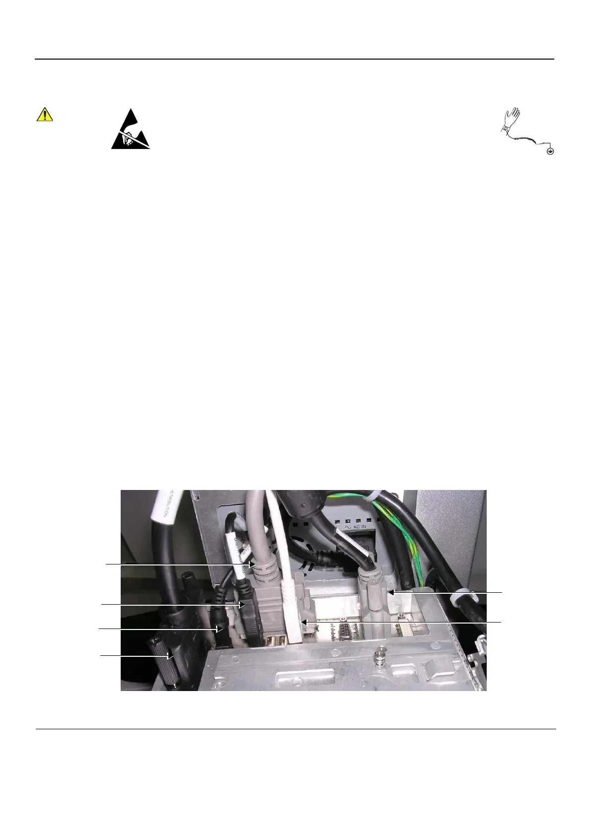
6) Unplug each of the six internal cables from the DIB Box, as shown in Figure 8-218 below.
When performing these procedures, take precautions to avoid damage of
electrostatic-sensitive components. Always have the ESD wrist strap
connected either to the DIB chassis or to the GND plug at the rear of the
scanner, and to your hand.
If a battery is present, first remove the battery as it contains stored energy.
Refer to 8-6-2-4 "Battery Removal Procedure" on page 8-116.
Figure 8-218 Cables Connected to DIB Box
DVI DVR
(J20)
USB Printer
(J15A)
USB
(J14A)
Display PWR
(J11)
AC Box
(J7)
KB Data
(J1)

 Loading...


