GE
P
ART NUMBER FN091065, REVISION 2 VS5 N AND VS6 N SERVICE MANUAL
Chapter 8 - Replacement Procedures 8-189
PRELIMINARY
Section 8-7
Mechanical Components Replacement Procedures
8-7-1 Foot Rest Replacement Procedure
8-7-1-1 Tools
None
8-7-1-2 Preparations
None
8-7-1-3 Foot Rest Removal Procedure
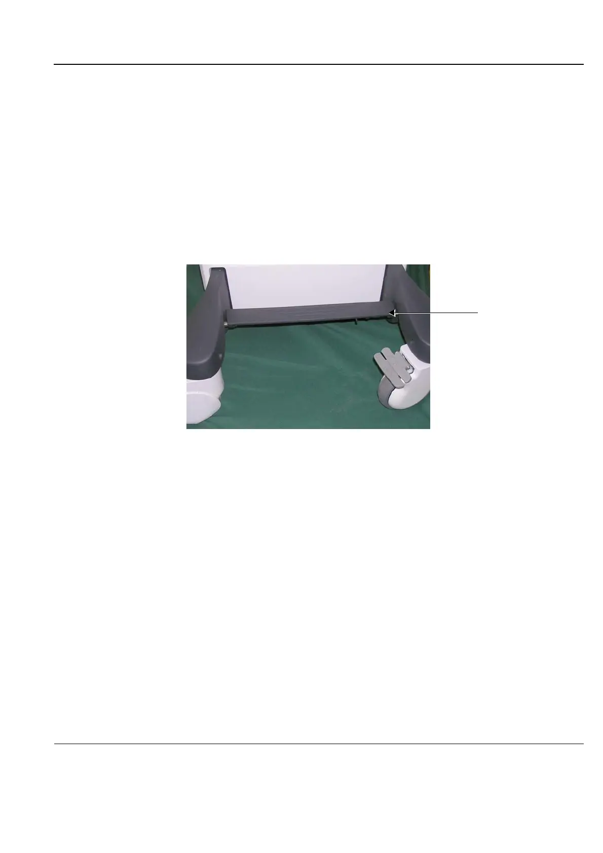
NOTE: The Foot Rest is secured in position on the front of the system, between the wheelbase:
1) Working from the front of the system, slide the spring-loaded bolt hinge (located underneath the foot
rest on the right side) towards the left and release the right side of the foot rest from the wheelbase,
as indicated in Figure 8-239.
Figure 8-238 Foot Rest in Position on the System

 Loading...


