Servo Drive Configuration D1 Servo Drive User Manual
5-22 HIWIN MIKROSYSTEM CORP.
Figure5.2.4.2
(2) Velocity mode
For controller which sends analog command or PWM command, select velocity mode. The ratio
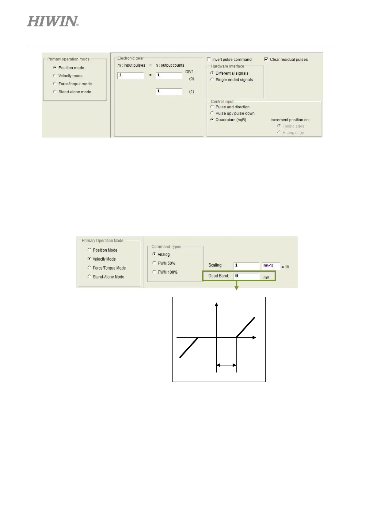
(scaling) between external command and velocity can be set in the setting page in figure 5.2.4.3. Set
1 V equals what velocity in mm/s (linear motor) or rpm (torque motor). User can also set the
corresponding velocity of full PWM. If a negative value is set for Scaling, the motor moves in
negative direction.
Figure5.2.4.3